

Low noise air blower unit for inflating thermal blankets
a blower unit and low noise technology, applied in the direction of machines/engines, liquid fuel engines, lighting and heating apparatus, etc., can solve the problems of not quieting the blower unit itself, affecting any electronic components housed in the cabinet, and may be sensitive to nois
Inactive Publication Date: 2001-07-03
GEN ELECTRIC CAPITAL
View PDF17 Cites 129 Cited by
- Summary
- Abstract
- Description
- Claims
- Application Information
AI Technical Summary
Problems solved by technology
Some patients, for example, may be sensitive to noise due to their particular medical conditions.
This approach, however. does not quiet the blower unit itself.
If the motor is not in the airstream, waste heat from the motor can accumulate in the cabinet, affecting any electronic components housed in the cabinet.
Passing air through a b,eater within a conduit usually results in "channeling" and uneven heating of the air.
Sound waves, which follow substantially straight paths, wherein directed around a bend or along a serpentine path reflect off the walls of the pathway and lose energy.
Method used
View moreImage
Smart ImageViewing Examples

Examples
Embodiment Construction
While there have been shown what are presently considered to be preferred embodiments of the invention, it will be apparent to those skilled in the art that various changes and modifications can be made herein without departing from the scope of the invention as defined by the appended claims.
Login to View More PUM
 Abstract
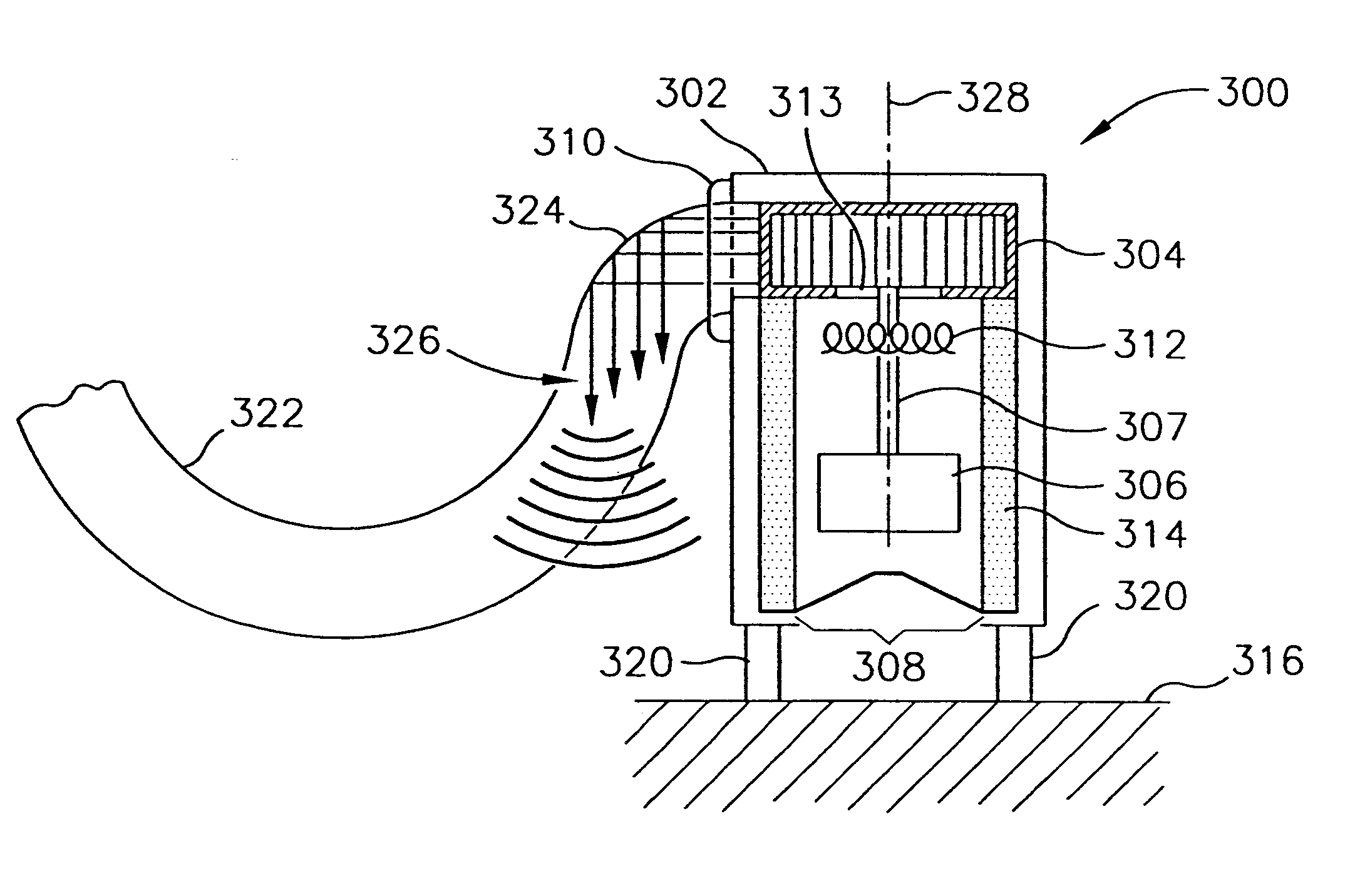
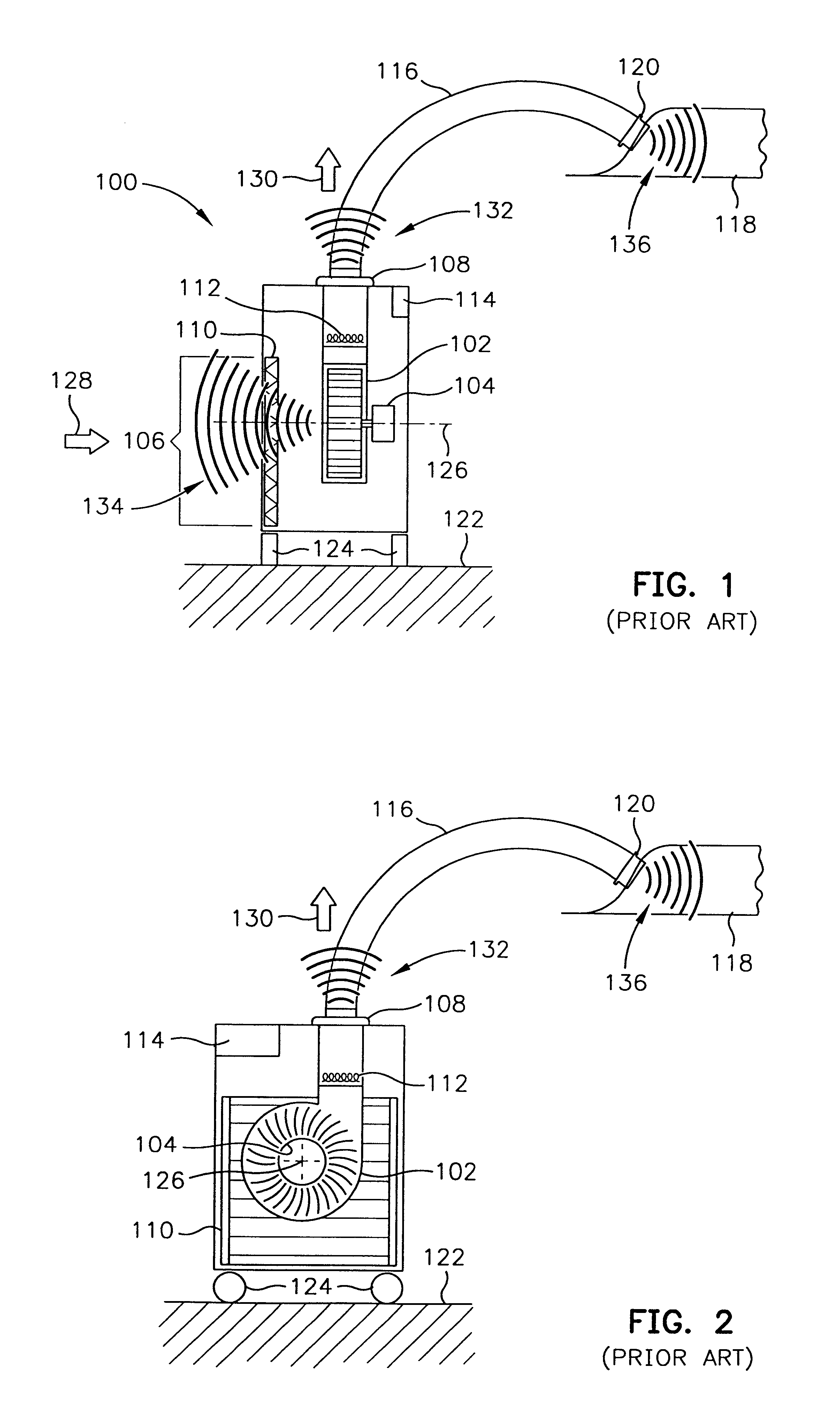
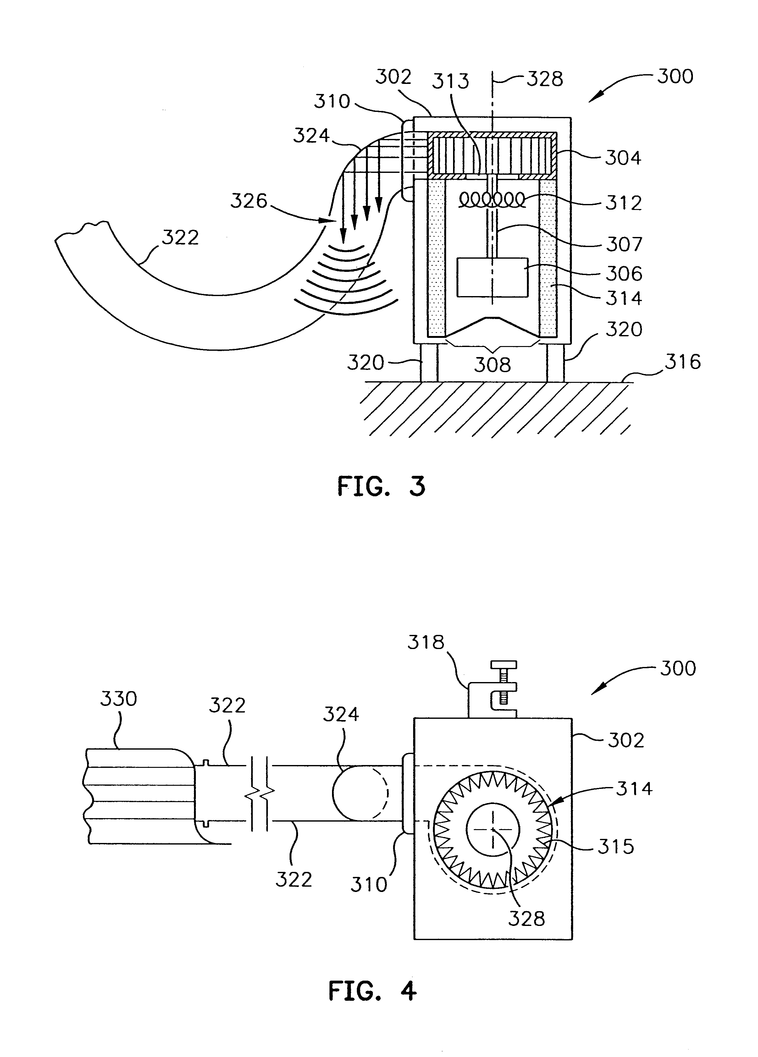
An air blower unit operates with reduced noise while providing a stream of warmed air. The blower unit includes a housing with an inlet at a first end and an outlet at a second end. A support positions the housing above a support surface such that the inlet points toward the support surface, and the outlet does not point away from the support surface. A rotatable blower creates an airstream by flowing air into the housing through the inlet and out of the housing through the outlet. The outlet is coupled to a delivery conduit having an elbow that absorbs some noise from the blower, and reflects remaining noise downward. The delivery conduit may be connected to a convective thermal blanket, for example. A motor, mechanically linked to the blower, rotates the blower and resides in the housing upstream of the blower. A heater, interposed between the blower and the motor, heats the fluid stream as it passes the heater.
Description
1. Field of the InventionThe present invention concerns a low-noise air blower unit that produces a stream of warmed air to inflate a thermal blanket.2. Description of the Related ArtAugustine, et al. first described the use of temperature-controlled forced air to regulate 10 the body temperature of patients, especially during and after surgery. U.S. Pat. No. 4,572,188, for example, used convective warming to prevent or treat hypothermia. In the '188 patent, temperature-controlled air is supplied by a blower unit that is connected to an airflow cover by a hose. In later-issued patents owned by the assignee of this application, the term "inflatable thermal blanket", synonymous with "airflow cover", is introduced. See, for example, U.S. Pat. No. 5,324,320, for "Thermal Blanket".Inflatable thermal blankets assume a variety of shapes and sizes for specialized use. and include various inflatable structures that wrap around or drape over a patient. See, for example, U.S. Pat. Nos. 5,300,1...
Claims
Login to View More Application Information
Patent Timeline
 Patent Type & AuthorityPatents(United States)
IPC IPC(8): F04D29/58F04D29/66F24H3/04
CPCF04D29/582F24H3/0405F04D29/663
InventorARNOLD, RANDALL C.
OwnerGEN ELECTRIC CAPITAL