Flexible joint and long nut for flexible joint

Inactive Publication Date: 2001-07-10
TAISEI KIKO
View PDF10 Cites 41 Cited by
  • Summary
  • Abstract
  • Description
  • Claims
  • Application Information

AI Technical Summary

Problems solved by technology

If such external force is too great, stress is concentrated on a tube joint which connects the tubes, and the tube joint is destroyed.
However, since this tube only telescopically moves, the movable region is two dimensional, and this tube can not sufficiently cope with the external force due to ground subsidence or earthquake.
However, since the tube joint itself has the telescopic flexibility, when the water pressure test is carried out prior to use or when the tube joint is being transported and moved, various members constituting the joint are moved by vibration.
For this reason, it is troublesome to handle the tube joint before the tube joint is connected to the tube, and it is not convenient for actual use.
However, in this structure, since the long nut used here is provided with the through hole and the rod is threaded into the through hole, there is a possibility that the long nut is not necessarily be constantly located over the longitudinal direction of the joint.
That is, two to four rods are disposed around the tube joint and position of each rod is not

Method used


Image

  • Flexible joint and long nut for flexible joint
  • Flexible joint and long nut for flexible joint
  • Flexible joint and long nut for flexible joint

Examples


Embodiment Construction

]

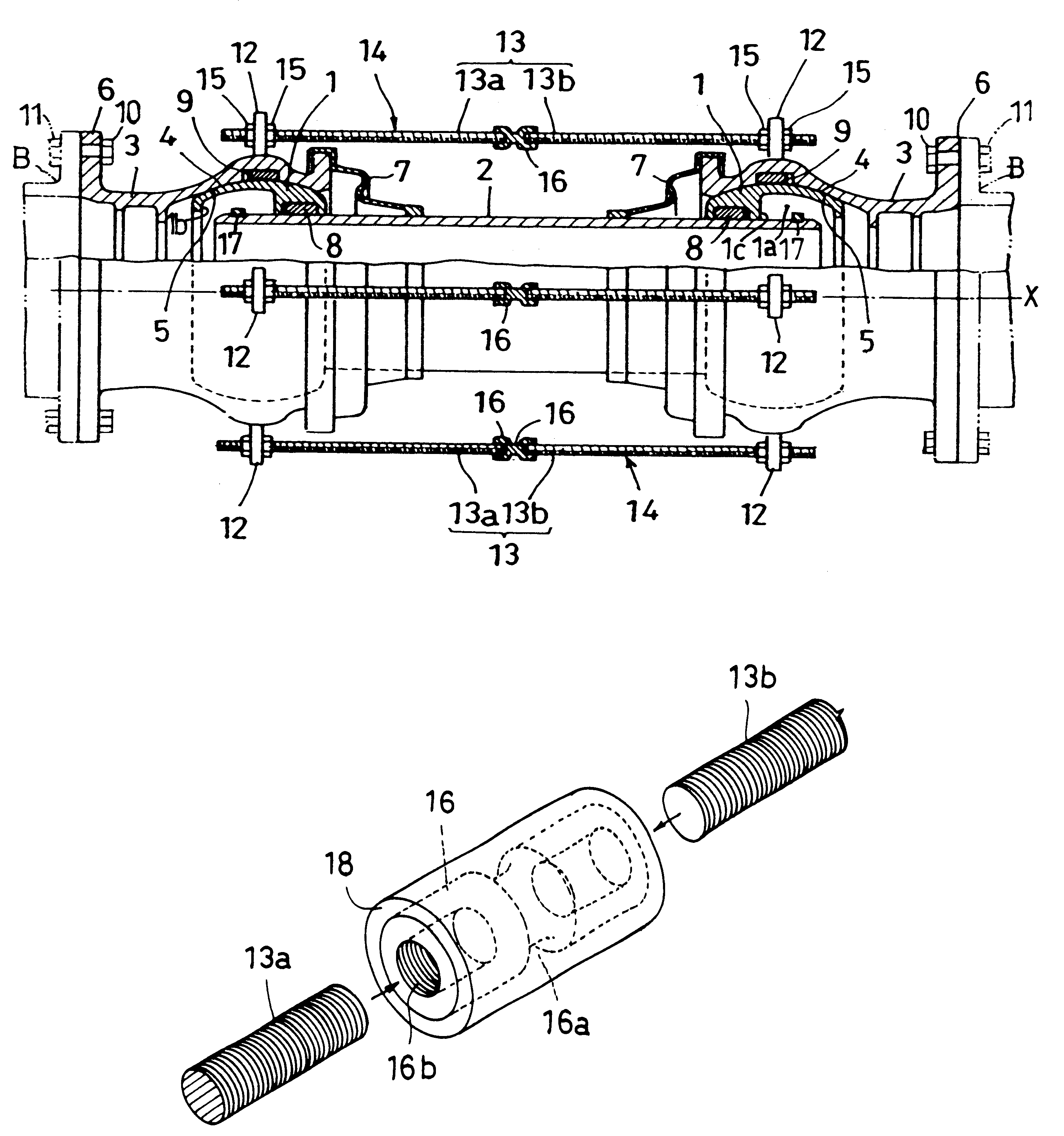
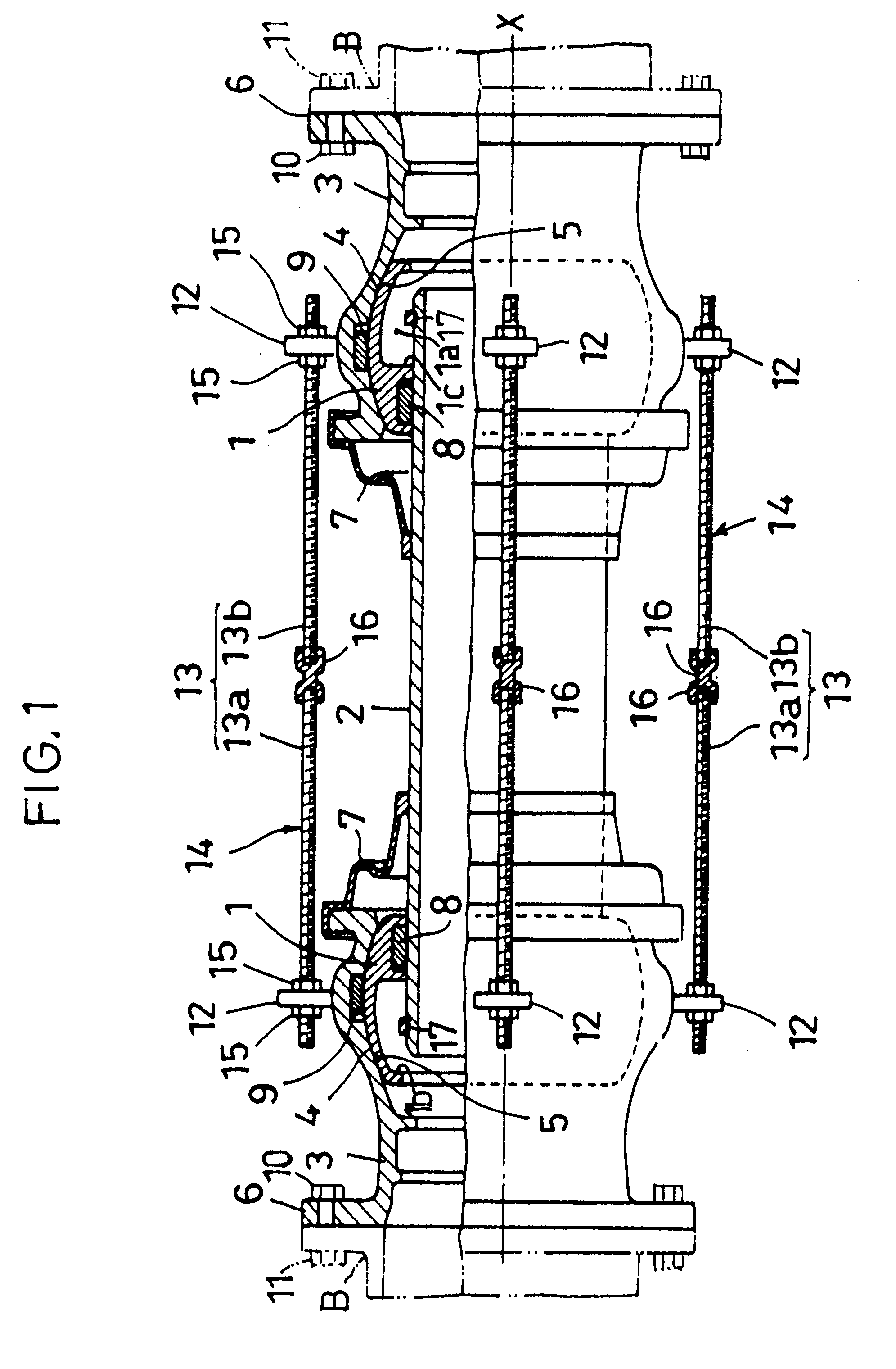
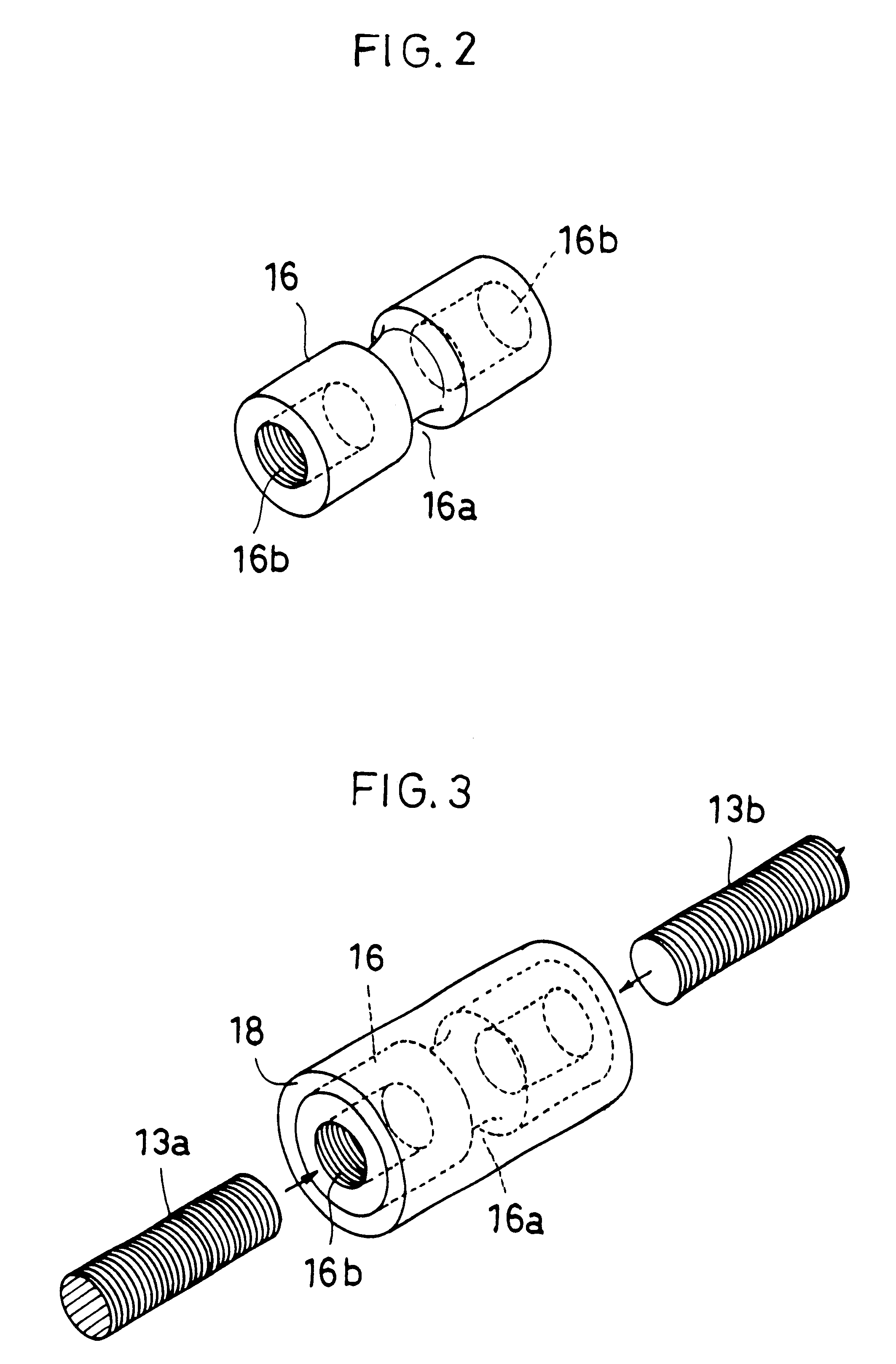
(a) FIG. 5 shows a sectional structure of a telescopic flexible tube joint A' according to another embodiment. This tube joint A' comprises first cylindrical bodies 21 and third cylindrical bodies 3. Each of the first cylindrical bodies 21 comprises a spherical portion 21a and a straight tube portion 21b. Each of the third cylindrical bodies 3 has substantially the same shape as that of the previous embodiment. An outer peripheral surface of the spherical portion 21a of the first cylindrical body 21 and an inner peripheral surface 5 of the spherical portion of the third cylindrical body 3 are slidingly contacted with each other. Such a sliding structure between the first cylindrical body 21 and the third cylindrical body 3 is provided on left and right sides on each. The straight tube portions 21b of both the first cylindrical bodies 21 are maintained in water-tightly sealed state by a rubber seal ring 23. As in the example shown in FIG. 1, a plurality of projections 12 are provide...


PUM


Abstract

A flexible joint comprises: first cylindrical bodies comprising a pair of spherical ring members; a second cylindrical body comprising a sleeve relatively movably inserted in the first cylindrical bodies from an axial direction X of the second cylindrical body; third cylindrical bodies comprising a pair of casing tubes which are fitted around outer peripheral surfaces of the first cylindrical bodies and are provided with mutually slidable spherical inner peripheral surfaces, the casings being formed at their opposite ends with connecting portions, and being provided at their outer peripheral surfaces of large diameter portions with projections having through holes; and rods capable of being inserted into the through holes formed in the outer peripheral surfaces of the large diameter portions, each of the rods being provided and fixed between the projections of the pair of third cylindrical bodies for restricting the telescopic movement of the tube joint, wherein the rods comprise a pair of rods connected to each other in the vicinity of a substantially central portion between the opposed projections, the pair of rods being threadedly connected to at least one of bottomed holes opened and formed on opposite ends of a long nut which is provided at its substantially central portion with a notched portion so that when excessive external force is applied, the notched portion is preferentially broken to restore telescopic flexible effect of the tube joint.

Description

1. Field of the InventionThe present invention relates to a flexible joint and a long nut for flexible joint, and more particularly, to a telescopic flexible tube joint which is used for connecting a water pipe and is capable of absorbing external force even if excessive external force is applied and thus, is capable of preventing the tube from being destroyed, and is easily handled, and to a long nut used for such a telescopic flexible tube joint.2. Description of the Related ArtTubes such as long water pipes laid on or under the ground are subjected, in some cases, to various external force such as compression force and tensile force in a direction of the core of the tube shaft due to ground subsidence or earthquake, and shearing force and bending moment. If such external force is too great, stress is concentrated on a tube joint which connects the tubes, and the tube joint is destroyed. Thereupon, it is necessary to absorb the external force applied to the water pipe portion to p...

Claims


Application Information

Patent Timeline
IPC IPC(8): F16L27/12
CPCF16L27/12F16L27/026F16L27/12751
Inventor KITANI, KENJIKITAMURA, MASARUFUJITA, YASUSHI
Owner TAISEI KIKO
Why Eureka
Try Eureka