
Ring oscillator having variable coarse and fine delays

a delay and ring oscillator technology, applied in pulse generators, pulse manipulation, pulse techniques, etc., can solve problems such as problems such as problems such as jitter, difficulty in compensating variations of delay of ring oscillators, and difficulty in achieving effective compensation in digital pll circuits

Inactive Publication Date: 2001-07-10
RENESAS ELECTRONICS CORP
View PDF6 Cites 55 Cited by
  • Summary
  • Abstract
  • Description
  • Claims
  • Application Information

AI Technical Summary

Problems solved by technology

However, it is difficult to compensate variations of delay of the ring oscillator caused by the fabrication process thereof between chips in a wafer or between lots or variations caused by environmental conditions of the ring oscillator.
That is, the design for compensation of the variations at least increases the design steps for the ring oscillator, and yet effective compensation for the variations is difficult to achieve in the digital PLL circuit.
In the conventional ring oscillator, there is a problem in that the variations of the first delay or the second delay due to variations in the fabrication process may increase the first delay or may reduce the second delay step so that the total of the second delays is lower than the first delay.
In this case, the variations generate a larger delay step at the shift stage of the ring oscillator when the ring oscillator shifts the delay step of the coarse delay control block by one step, whereby the oscillator frequency fluctuates at the shift stage and a problem jitter is involved.

Method used


Image

  • Ring oscillator having variable coarse and fine delays
  • Ring oscillator having variable coarse and fine delays
  • Ring oscillator having variable coarse and fine delays

Examples


Embodiment Construction

Now, the present invention is more specifically described with reference to accompanying drawings.

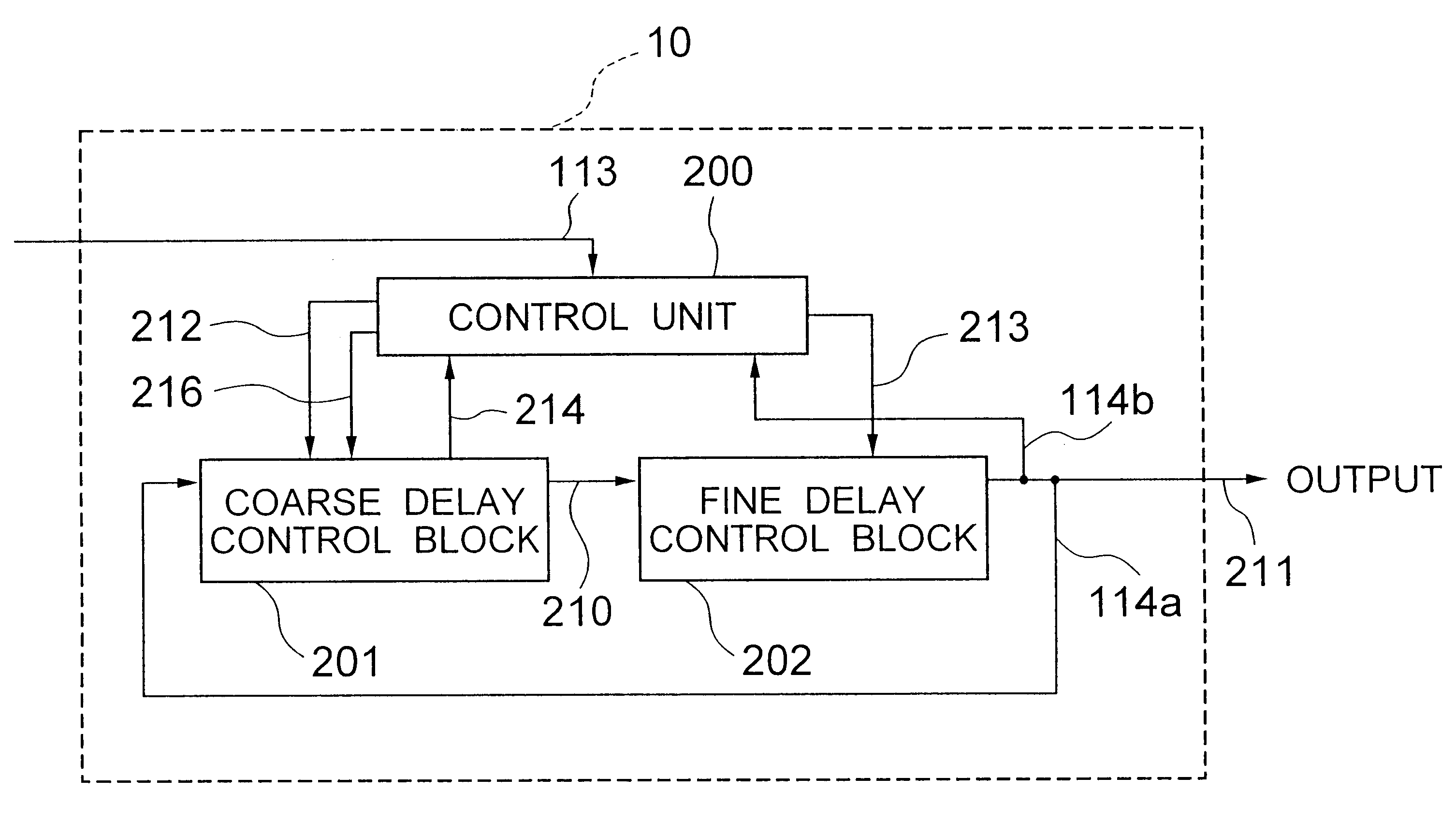
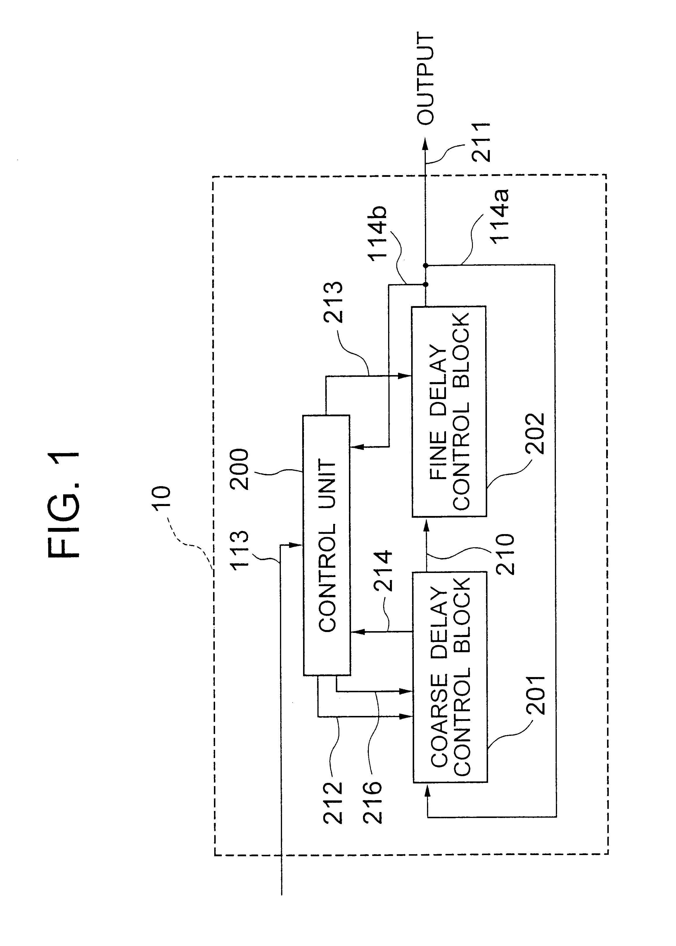
Referring to FIG. 1, a ring oscillator, generally designated by numeral 10, according to an embodiment of the present invention includes a coarse delay control block 201 for generating a coarse delay with respect to the phase of an input signal 114a supplied thereto, a fine delay control block 202 for generating a fine delay with respect to an output signal 210 from the coarse delay control block 201, and a control unit 200 for receiving an external control signal 113 supplied from outside the ring oscillator 10 to generate a pair of control signals 212 and 216 for controlling the coarse delay control block 201 and a control signal 213 for controlling the fine delay control block 202. An output signal from the fine delay control block 202 is fed-back as the input signal 114a of the coarse delay control block 201. The output signal 114a of the fine delay control block 202 is delivered as...


PUM


Abstract

A ring oscillator includes a coarse delay control block including a plurality of coarse delay gates, and a fine delay control block including a plurality of fine delay gates. The total delay of the fine delay control block is larger than a single delay step of the coarse delay control block, whereby variations of the delay step do not cause an adverse effect on the jitter characteristic of a PLL circuit having the ring oscillator. In a normal operation, the coarse delay control block increments the delay step after the total of the delay steps of the fine delay control block exceeds the delay step of the coarse delay control block.

Description

(a) Field of the InventionThe present invention relates to a ring oscillator having a variable delay and, more particularly, to a ring oscillator having a variable delay suitably used for a digital phase locked loop (PLL) circuit.(b) Description of a Related ArtA ring oscillator having a variable delay (delay time) is generally used in a digital PLL circuit as a voltage controlled oscillator (VCO).A Patent Publication JP-A-6-77782 describes a conventional ring oscillator having a variable delay, wherein the oscillation frequency range and the gain of the ring oscillator can be controlled. The ring oscillator includes a plurality of delay gates cascaded in a ring fashion. The delay gates are provided with a first control block for controlling the oscillation frequency of the delay gates at a coarse delay step by controlling the applied voltage or operational current of the delay gates. A second control bock is also provided for controlling the oscillation frequency of at least one of...

Claims


Application Information

Patent Timeline
IPC IPC(8): H03L7/087H03L7/099H03K3/011H03K3/00H03K3/03H03L7/08H03L7/089H03K3/354H03K3/023
CPCH03K3/011H03K3/0315H03L7/0997H03L7/087H03K5/131H03L7/089
Inventor ARAI, KOUJI
Owner RENESAS ELECTRONICS CORP
Learn More