Computer tomography device

Inactive Publication Date: 2001-07-10
US PHILIPS CORP
View PDF8 Cites 32 Cited by
  • Summary
  • Abstract
  • Description
  • Claims
  • Application Information

AI Technical Summary

Benefits of technology

For individual adjustments of the X-ray collimator it is possible to select substantially parallel cross-sections, having selectable transverse dimensions, for which density profiles are simultaneously measured. It is thus achieved that the dimensions of the part of the patient to be examined for which a volume scan is to be performed in one operation and the spatial resolution are selected by simple adjustment of the X-ray collimator. Consequently, a computer tomography device according to the invention is suitable for use for a wide variety of different radiological e

Problems solved by technology

Consequently, only a small amount of time is required to measure the d

Method used


Image

  • Computer tomography device
  • Computer tomography device
  • Computer tomography device

Examples


Embodiment Construction

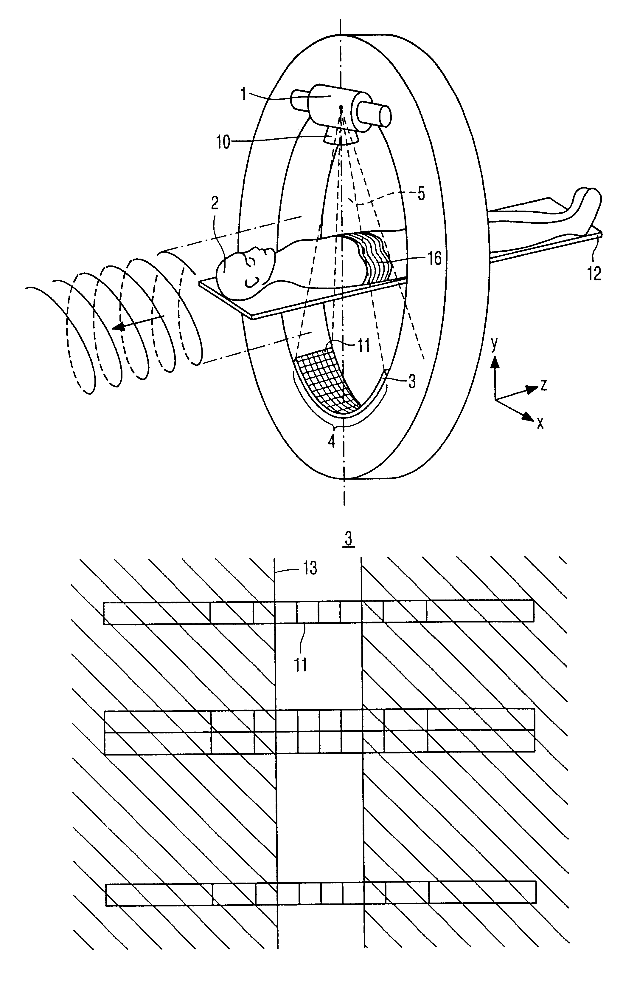
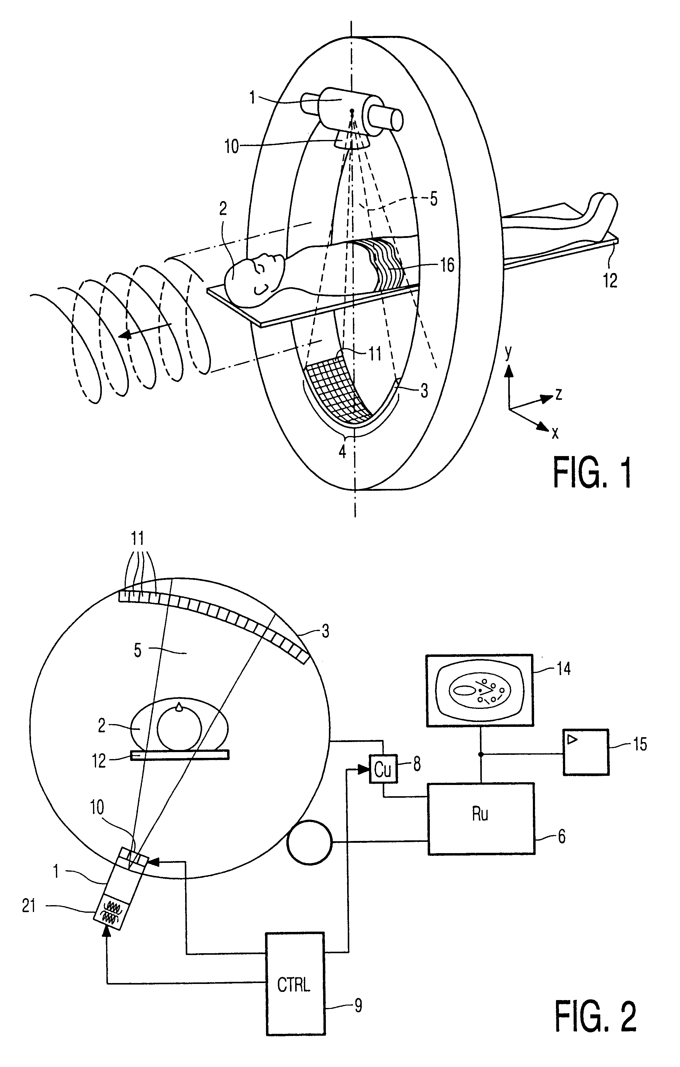
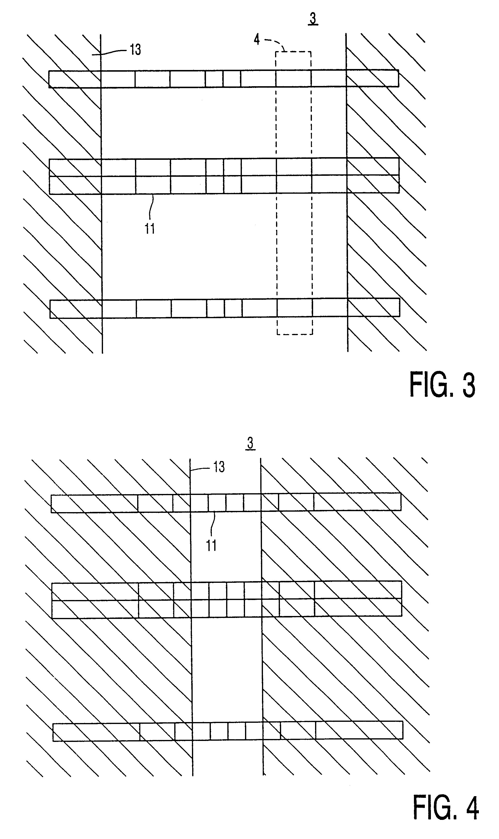
FIG. 1 is a three-dimensional diagrammatic representation of a computer tomography device according to the invention. FIG. 2 shows diagrammatically a computer tomography device according to the invention. In co-operation with an adjustable X-ray collimator, an X-ray source 1 produces a diverging, essentially cone-shaped X-ray beam for irradiating the object 2, for example a patient to be examined. The detector system 3 is arranged so as to face the X-ray source 1. The X-ray collimator 10 is constructed as a slit-shaped diaphragm 10 with a slit whose dimensions can be adjusted. The thickness of the cone-shaped X-ray beam generally amounts to from 10 mm to 100 mm, measured halfway between the X-ray source and the detection system. The intensity of the radiation having passed the patient and incident on the detector system is determined predominantly by the absorption within the patient 2 who is arranged on a table 12 between the X-ray source and the detector system. By rotating the X-...


PUM


Abstract

The computer tomography device includes an X-ray source for emitting an X-ray beam and a detector system for measuring density profiles of cross-sections of an object. The detector system includes a two-dimensional matrix of detector elements. The detector elements positioned along a direction transversely of the cross-sections have the same effective surface and detector elements positioned parallel to the cross-sections have different effective surfaces. Furthermore, the computer tomography device includes an adjustable X-ray collimator for limiting the X-ray beam transversely of the cross-sections.

Description

BACKGROUND OF THE INVENTION1. Field of the InventionThe invention relates to a computer tomography device which includes an X-ray ray source for emitting an X-ray beam and a detector system for picking up density profiles of cross-sections of an object to be examined.2. Description of Related ArtA computer tomography device of this kind is known from the article "Computed tomography scanning with simultaneous patient translation" by Carl R. Crawford and Kevin F. King in Medical Physics 17 (1990), 967-982.Computer tomography involves the formation of images of cross-sections of the object to be examined, for example a patient to be radiologically examined. To this end, the patient is irradiated by means of X-rays from different directions and, due to local differences in the X-ray absorption within the patient, density profiles are formed for the various directions, said profiles being measured by the detector system. To this end, the X-ray source and the detector system are rotated ...

Claims


Application Information

Patent Timeline
IPC IPC(8): A61B6/03G01T1/00G01T1/202G01T1/29
CPCA61B6/032G01T1/2985G01T1/202A61B6/4085A61B6/027A61B6/4028
Inventor CUPPEN, JOHANNES J. M.
Owner US PHILIPS CORP
Why Eureka
Try Eureka