Contacting device for a chip card and in particular for a SIM card

a technology of contacting device and chip card, which is applied in the direction of coupling device connection, printing, and sensing record carrier, etc., can solve the problem of separate drawers getting los

Inactive Publication Date: 2001-07-17
AMPHENOL TUCHEL ELECTRONICS
View PDF2 Cites 107 Cited by
  • Summary
  • Abstract
  • Description
  • Claims
  • Application Information

AI Technical Summary

Benefits of technology

In accordance with another embodiment of the present invention, there is provided a contacting device comprising a stationary base and a movable slider, wherein the chip card is slidable between an insert / removal position and a reading position, wherein a metal cover is fixedly mounted to the contacting device for providing support for the chip card so as to provide reaction forces taking up contacting forces exerted by contacting elements of the contacting device. Preferably, the contacting device has a plenum or card receiving space for receiving the chip card, and the metal cover spans the card plenum as well as the slider and extends or reaches around the sides of the base. By using a metal cover, a particularly small thickness is possible for the cover. Further, the metal cover is easy to manufacture and to assemble.
According to another preferred embodiment of the invention, the slider is slidably arranged at the side and in longitudinal direction of the contacting device next to the inserted chip card. Since the chip card and the slider are not overlapping as seen in a top plan view, a particularly small thickness or height of the contacting device is possible.
Further, an outer end of the slider, i.e. an end extending outside of the contacting device when said slider is extracted or pulled out from the contacting device, may be flush with the contacting device or its contour in the reading position of the chip card. Thus, mounting of the contacting device is easily possible even at locations where projecting elements must be avoided. For example, the contacting device may be mounted in a mobile telephone at a location which is accessible from the battery bay such that the battery pack may be inserted or put into place with the slider being the retracted position, i.e. with the chip card being in the reading position; the battery pack then covers the contacting device and protects it from access or dirt.
For improved guidance of the slider within the contacting device, the base of the contacting device comprises a recess forming a track for the slider. On said track, a projection or pin may be provided which extends into an elongate recess in the slider. The projection or pin may limit movement of the slider in direction of sliding (or extraction / retraction) by coming into abutment with one or the other end of the elongate recess in the slider. Further, the projection and recess provide additional guidance for the slider.

Problems solved by technology

With this design the separate drawer may get lost.

Method used


Image

  • Contacting device for a chip card and in particular for a SIM card
  • Contacting device for a chip card and in particular for a SIM card
  • Contacting device for a chip card and in particular for a SIM card

Examples


Embodiment Construction

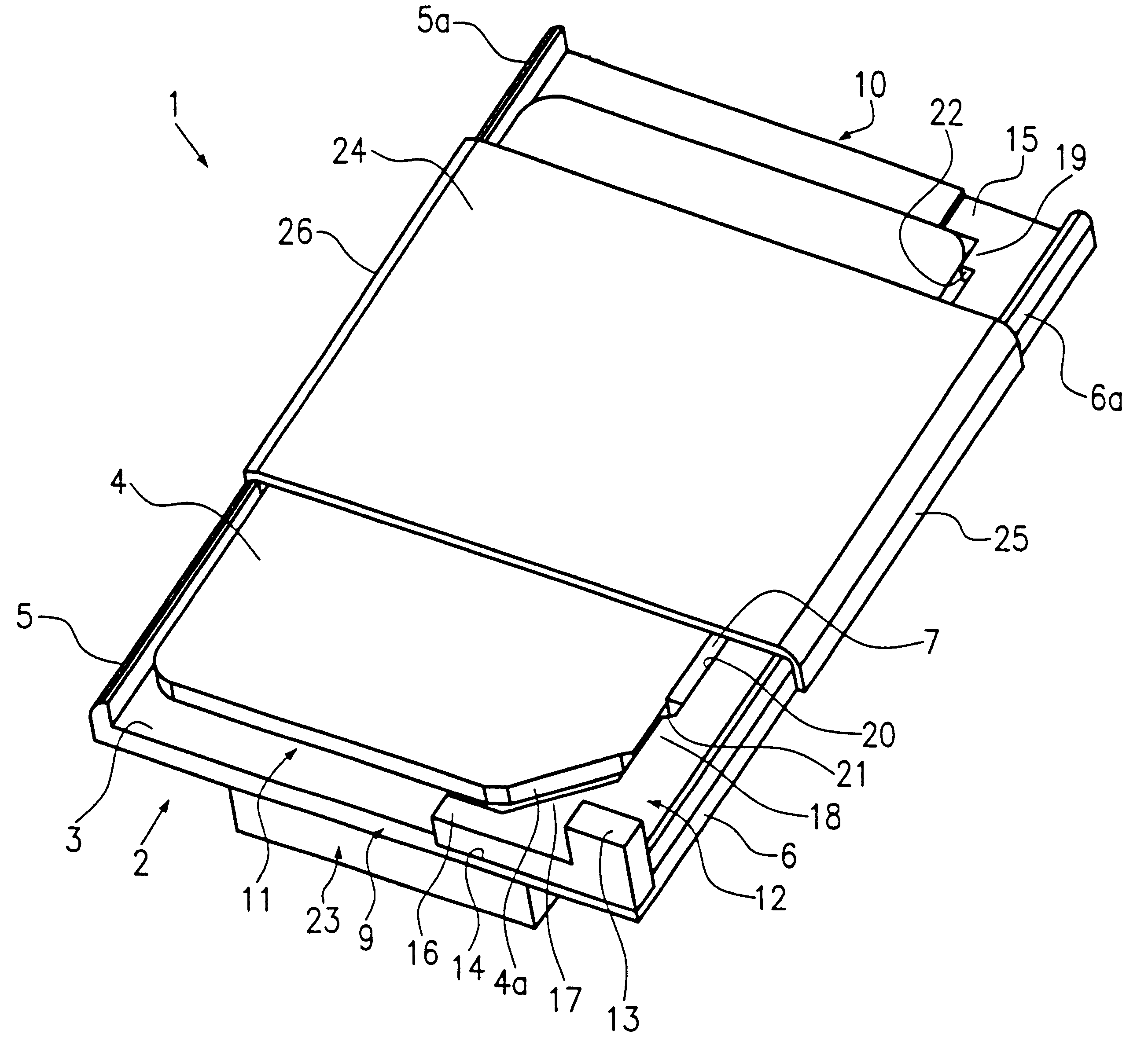
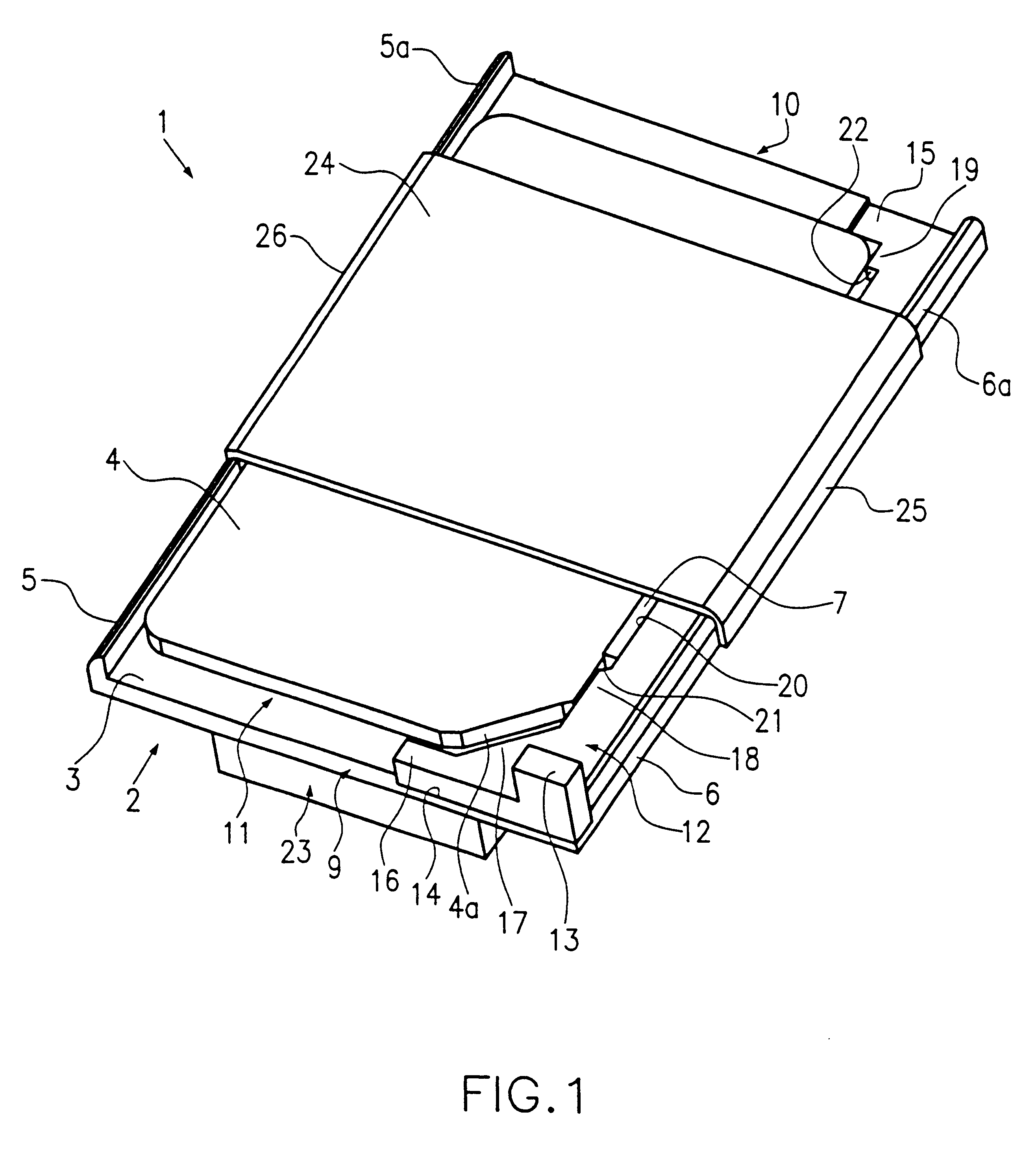
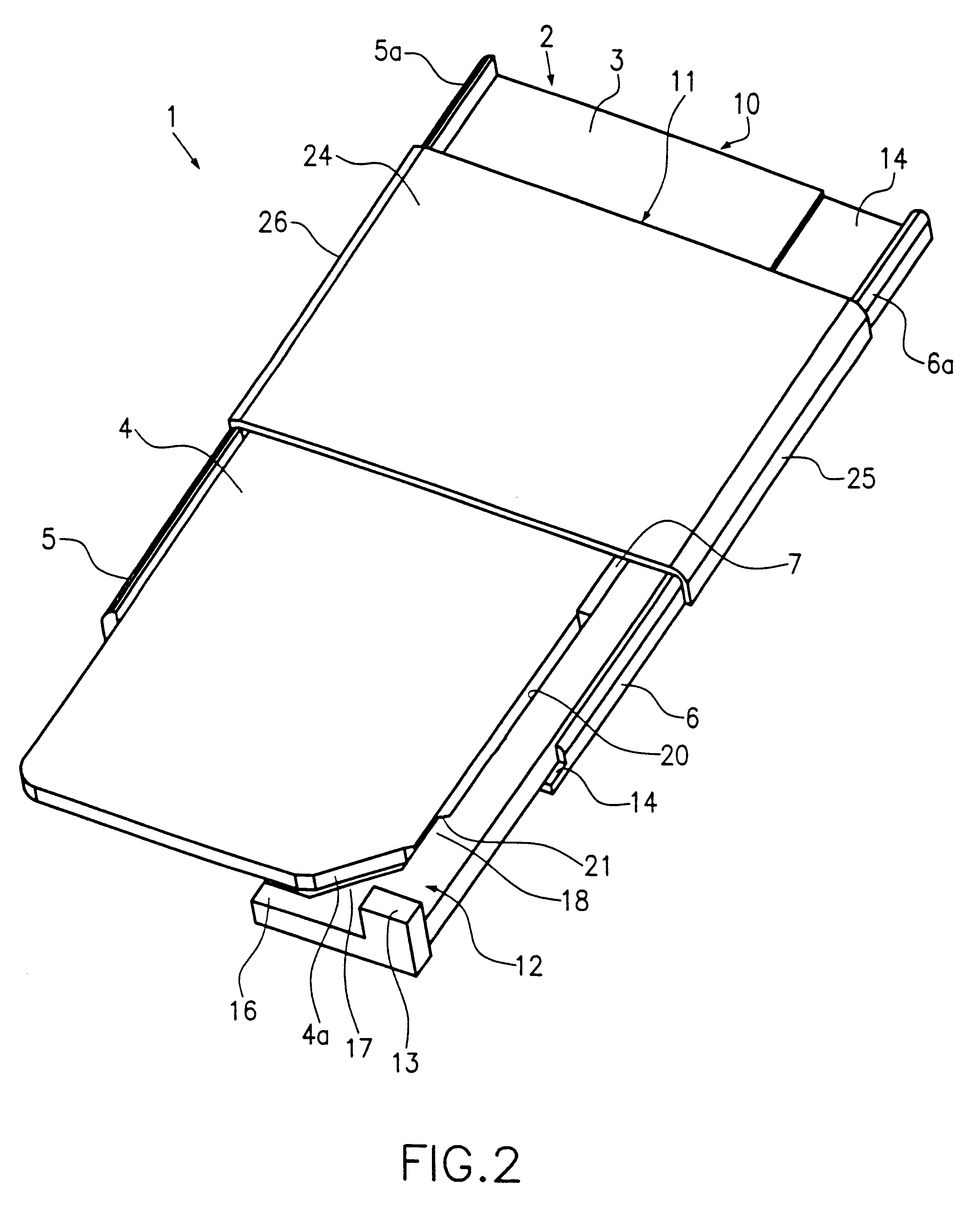
FIGS. 1-4 show a contacting device comprising a base including contacting elements, a cover and a movable slider. The contacting device has a reading position as shown in FIG. 1 and a card insert / removal position shown in FIG. 2. The contacting device 1 has a stationary base 2 with a support surface 3 for a SIM card 4. The base 2 is preferably a plastic injection molded part. At one longitudinal side of the base 2 the support surface 3 is bordered by a flange-like first side wall 5 with said first side wall 5 providing lateral guidance for the SIM card 4. The first side wall 5 extends preferably along the entire length of the base 2 and has a height extending above the support surface 3 which corresponds approximately to the height or thickness of a SIM card 4 placed on said support surface 3. At the opposite longitudinal side of the base 2, a second side wall 6 is provided which is also of a flange-like design and preferably has the same height as the first side wall 5. The distanc...


PUM


Abstract

There is provided a contacting device (1) for chip cards, preferably for SIM cards, comprising a base (2), a slider (12) arranged at the base (2) and being movable with respect to the base (2), the chip card (4) being slidable between an insert / removal position and a reading position by means of said slider, and means (7, 22) for inhibiting removal of the slider from the contacting device (1). Preferably, the slider (12) is slidably mounted to the base (2) and is in abutting engagement with an abutment in the insert / removal position such that the slider (12) cannot be removed from the contacting device (1), i.e. the slider (12) cannot be moved beyond the insert / removal position. Thus, the contacting device does not comprise any loose parts that could get lost. In accordance with another embodiment of the present invention, there is provided a contacting device (1) for a chip card (4) comprising a stationary base (2) and a movable slider (12), wherein a chip card (4) is slidable between an insert / removal position and a reading position, wherein a metal cover (24) is fixedly mounted to the contacting device (1) and for providing support for the chip card (4) for providing counter-forces taking up contacting forces between contacting elements of the contacting device (1) and contacting pads of the chip card. Preferably, the contacting device (1) has a card plenum (11) for receiving the chip card (4), and the metal cover (24) spans the card plenum (11) as well as the slider (12) and extends around the sides of the base (2). By using a metal cover, a particularly small thickness is possible for this component. Further, the metal cover is easy to manufacture and to assemble.

Description

1. Field of the InventionThe present invention relates to a contacting device for a chip card and in particular for a SIM (subscriber identity module) card. Chip cards and / or SIM cards are also known as smart cards.2. Description of Related ArtContacting devices for chip cards are known in the art. Such contacting devices are also known as chip card readers or smart card readers, or in particular when used with SIM cards, as SIM card readers. With many slide-in approaches for SIM cards such as cards having the ID-000 format for mobile telephones, the SIM card conventionally is inserted or placed in a kind of loose or separate drawer or cover, and the drawer is slid into a slot opening of the contacting device. With this design the separate drawer may get lost. Further, the drawer and the contacting device must comprise some kind of guide means for guiding the drawer in the contacting device, such guide means requiring additional space with respect to height and width. Moreover, ejec...

Claims


Application Information

Patent Timeline
Patent Type & Authority Patents(United States)
IPC IPC(8): G06K13/02G06K13/08G06K7/00B42D15/10G06K17/00H01R12/18H01R13/639
CPCG06K7/0021G06K13/0831G06K13/08
Inventor HEIM, MICHAELLAAGE, ANDREAS
Owner AMPHENOL TUCHEL ELECTRONICS
Why Eureka
Try Eureka