Plasma processing device for surfaces

a technology of surface treatment and plasma, which is applied in the direction of coatings, electrical appliances, arc welding equipment, etc., can solve the problems of insufficient uniformity of pretreatment in the stripe being swept, and achieve the effect of low equipment expenses and rapid and efficient pretreatment of larger surfaces

Inactive Publication Date: 2001-07-24
PLASMATREAT GMBH
View PDF11 Cites 92 Cited by
  • Summary
  • Abstract
  • Description
  • Claims
  • Application Information

AI Technical Summary

Benefits of technology

It is an object of the invention to provide an apparatus for plasma surface treatment which permits a rapid and efficient pretreatment of larger surfaces at low equipment expenses. This object i

Problems solved by technology

In this context, it is tolerable that the intensity of the pre

Method used


Image

  • Plasma processing device for surfaces
  • Plasma processing device for surfaces
  • Plasma processing device for surfaces

Examples


Embodiment Construction

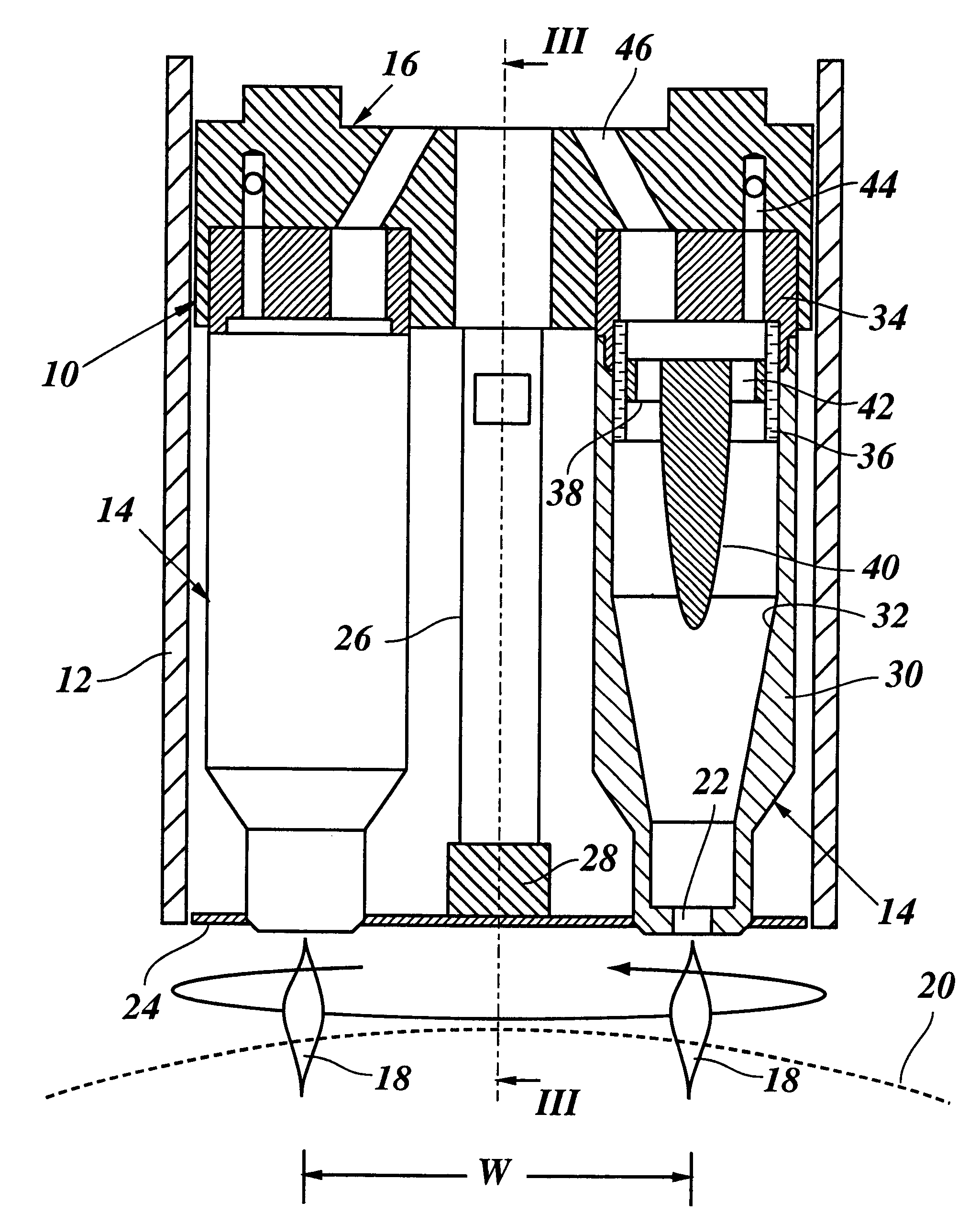
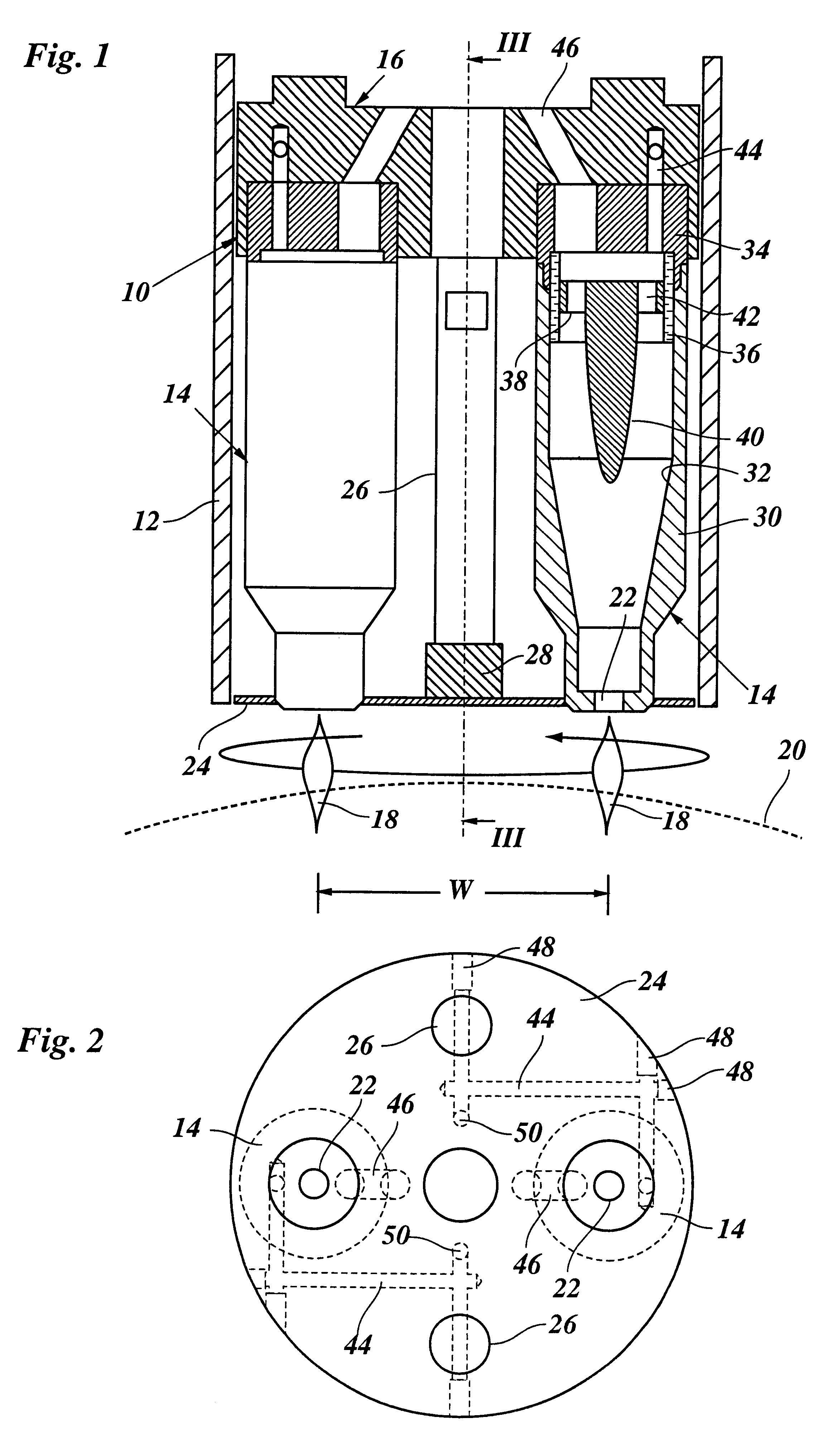
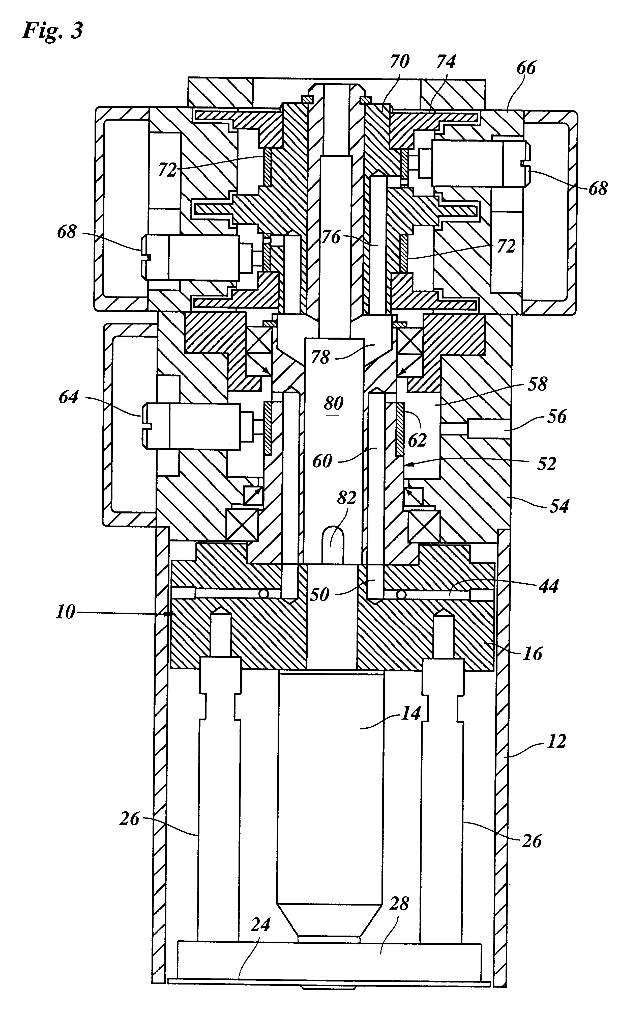
FIG. 1 shows a rotating head 10 which rotates about its central axis, which is the vertical axis in FIG. 1, and is surrounded by a stationary cylinder 12 serving as a protecting shield. The rotating head 10 has two diametrically opposed plasma nozzles 14 mounted to an annular distributor block 16 and arranged to emit plasma jets 18 in a direction in parallel with the axis of rotation. When the head 10 is moved relative to the surface of a workpiece 20 in a direction normal to the plane of the drawing in FIG. 1 and rotates with a high speed of revolution, the plasma jets 18 sweep relatively uniformly over a stripe on the surface of the workpiece having a width W of, for example, 8 cm.

The mouths 22 of the plasma nozzles are disposed in a common plane in a face plate 24 which is held co-rotatably at the distributor block 16 by two bars 26. The bars 26 are disposed in a plane normal to the plane of the plasma nozzles 14 and are connected with one another at the face plate 24 by a cross ...


PUM

PropertyMeasurementUnit
Electric potential / voltageaaaaaaaaaa

Abstract

A mechanism for plasma surface treatment includes a rotating head having at least one eccentrically disposed plasma nozzle for generating a plasma jet directed in parallel with the axis of rotation. The nozzle includes a swirl system for swirling the plasma jet.

Description

The invention relates to an apparatus for plasma treatment of surfaces. More particularly, the invention relates to a pretreatment enabling the coating of surfaces of synthetic resin materials with adhesives, printing inks and the like. Such a pretreatment is necessary because the surfaces of synthetic resins can normally not be wetted with liquids and do therefore not accept the printing ink or the adhesive. The pretreatment changes the surface structure of the synthetic resin so that it becomes wettable with liquids having a comparatively large surface tension. The surface tension of the liquids with which the surface can still be wetted is an indictor for the quality of the pretreatment.A well established method for the pretreatment of synthetic resin surfaces is based on the principle of corona discharge. In this method the resin to be treated is typically passed through between two electrodes which are coated with a ceramic material and to which a high voltage with high frequen...

Claims


Application Information

Patent Timeline
IPC IPC(8): B05D3/14B29C59/00B29C59/14H05H1/26H05H1/44H05H1/24C08J7/00H05H1/34
CPCB05D3/144H05H1/44B29C59/14
Inventor FORNSEL, PETERBUSKE, CHRISTIAN
Owner PLASMATREAT GMBH
Why Eureka
Try Eureka