
Refrigerant cycle system for vehicle air conditioner

Inactive Publication Date: 2001-07-31
HONDA MOTOR CO LTD
View PDF6 Cites 39 Cited by
  • Summary
  • Abstract
  • Description
  • Claims
  • Application Information

AI Technical Summary

Benefits of technology

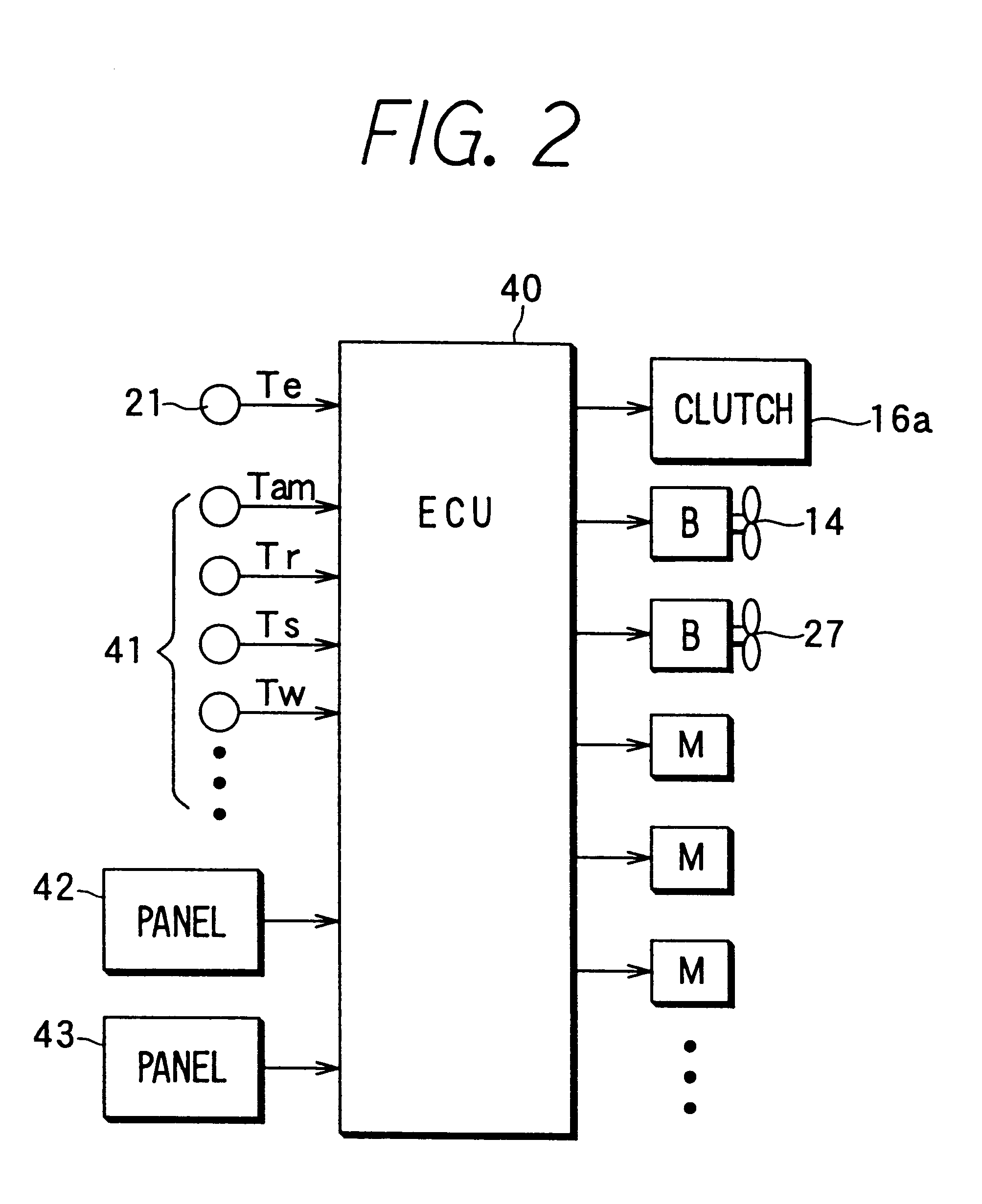
Thus, according to the present invention, a refrigerant cycle system including: a compressor for compressing and discharging refrigerant, a condenser for cooling and condensing gas refrigerant discharged from the compressor, a first pressure-reducing unit for decompressing and expanding liquid refrigerant from the condenser, a first evaporator for evaporating refrigerant from the first pressure-reducing unit, a first blower for blowing air toward the first evaporator, a second pressure-reducing unit for decompressing and expanding liquid refrigerant from the condenser, a second evaporator for evaporating refrigerant from the second pressure-reducing unit, and a second blower for blowing air toward the second evaporator. The second pressure-reducing unit is disposed parallel to the first pressure-reducing unit relative to a refrigerant flow direction, and the second evaporator is disposed parallel to the first evaporator relative to the refrigerant flow direction. In the refrigerant cycle system, a control unit controls operation of the compressor to change a refrigerant pressure at a suction side of the compressor when a continuous operation time of the compressor passes a predetermined time after the compressor operates, and the second pressure-reducing unit is a thermal expansion valve which adjusts a super-heating degree of refrigerant at an outlet of the second evaporator by adjusting a valve opening degree. Thus, even when the compressor continuously operates in a long time when only the first evaporator operates, the refrigerant pressure the suction side (low-pressure side) is forcibly changed. Therefore, it is possible to forcibly open the thermal expansion valve of the second evaporator. As a result, lubrication oil staying in the second evaporator, a low-pressure pipe and the like is returned to the suction side of the compressor with a refrigerant flow due to the forcibly opening of the thermal expansion valve. Accordingly, the refrigerant cycle system prevents an oil amount returning to a compressor from being insufficient without using an electromagnetic valve for the second evaporator, when only the first evaporator operates.
Preferably, the control unit controls an interruption operation of the compressor in accordance with an air temperature blown from the first evaporator. Therefore, it prevents the first evaporator from frosting.
Further, when the refrigerant cycle system is applied to a vehicle air conditioner having a front air-conditioning unit and a rear air-conditioning unit, an oil amount returning to the compressor is prevented from being insufficient when only the front air-conditioning unit operates.

Problems solved by technology

However, in a vehicle where an electromagnetic valve for the rear evaporator is not provided for reducing cost of the air conditioner, when a rear air-conditioning unit is stopped, a lubrication oil staying in the rear evaporator does not return to the compressor, and an oil amount returning to the compressor becomes insufficient.
As a result, durability of the compressor is deteriorated.

Method used


Image

  • Refrigerant cycle system for vehicle air conditioner
  • Refrigerant cycle system for vehicle air conditioner
  • Refrigerant cycle system for vehicle air conditioner

Examples


Embodiment Construction

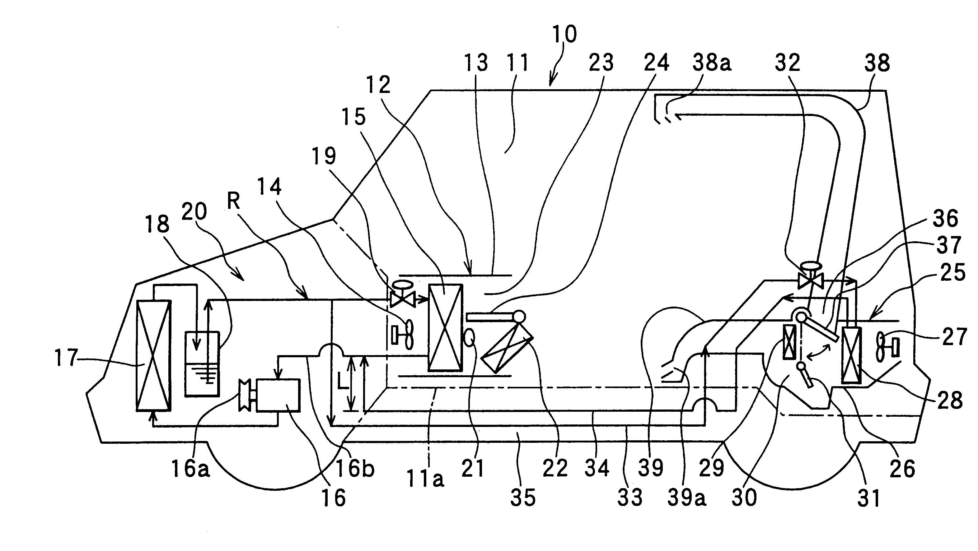
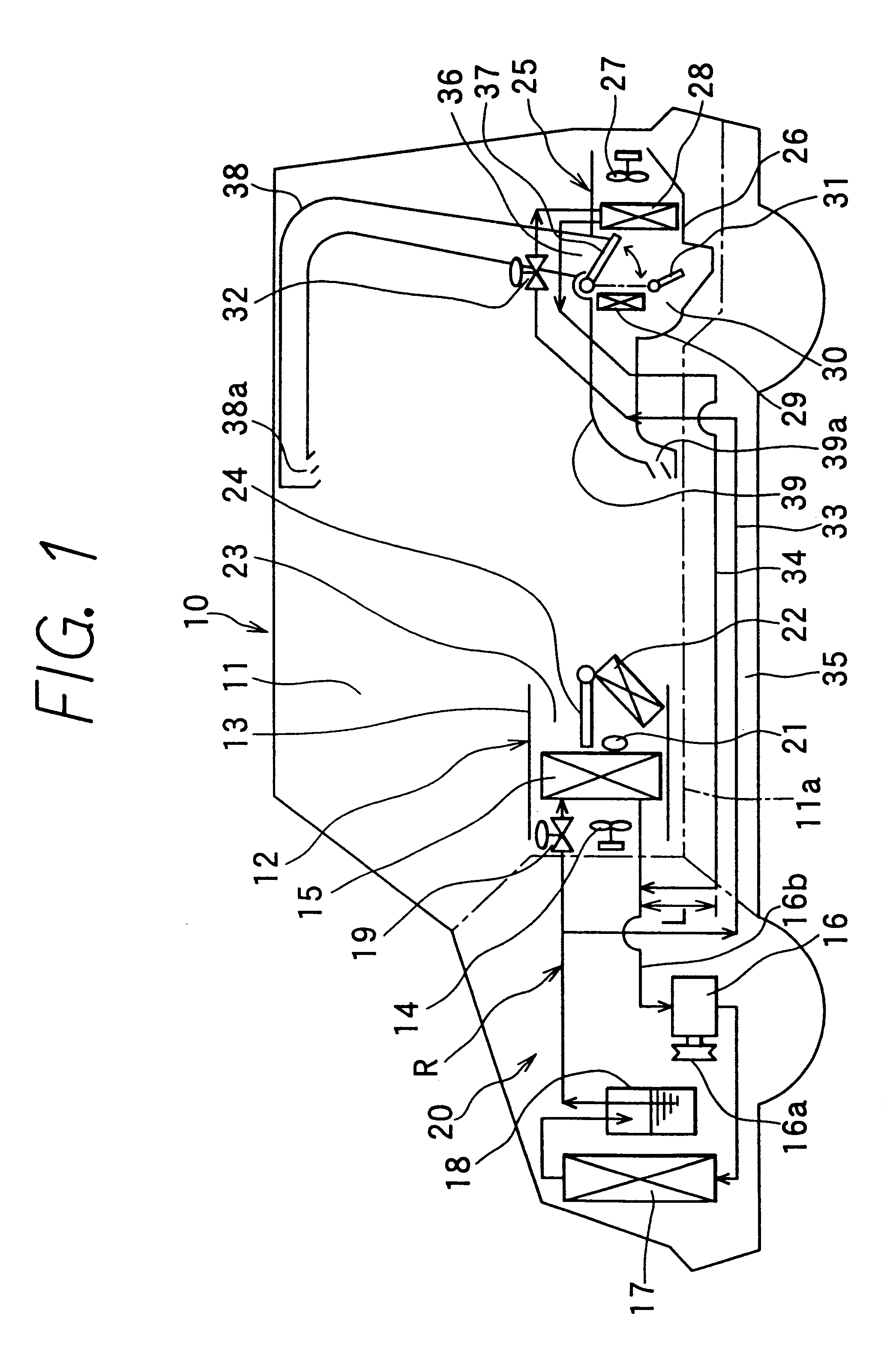
A preferred embodiment of the present invention will be described hereinafter with reference to the accompanying drawings. In the embodiment, the present invention is typically applied to an air conditioner for a minivan type vehicle. As shown in FIG. 1, a vehicle 10 having a passenger compartment 11 is provided with a front seat including a driver's seat and a front-passenger's seat, and a rear seat including the second and the third seats from the front seat. That is, a longer space is formed in the passenger compartment 11 in a vehicle front-rear direction. A floor surface 11a is provided in the passenger compartment 11.

The air conditioner includes a front air-conditioning unit 12 for adjusting an air state blown toward a front seat side of the passenger compartment 11, and a rear air-conditioning unit 25 for adjusting an air state blown toward a rear seat side of the passenger compartment 11. The front air-conditioning unit 12 is disposed within an instrument panel (not shown) p...


PUM


Abstract

In a refrigerant cycle system for a vehicle air conditioner, when a continuous operation time of a compressor elapses a predetermined time after the compressor operates, operation of the compressor is forcibly interrupted so that a refrigerant pressure at a suction side of the compressor is changed. Thus, even when the compressor operates continuously in a long time when only a front evaporator operates among front and rear evaporators, the refrigerant pressure at a low-pressure side is forcibly changed so that a rear thermal expansion valve of the rear evaporator is forcibly opened. As a result, lubrication oil staying in the rear evaporator and a low-pressure pipe is introduced into the suction side of the compressor by a refrigerant flow due to a valve opening of the rear thermal expansion valve of the rear evaporator.

Description

This application is related to and claims priority from Japanese Patent Application No. Hei. 11-89786 filed on Mar. 30, 1999, the contents of which are hereby incorporated by reference.1. Field of the InventionThe present invention relates to a refrigerant cycle system having first and second evaporators disposed parallel to each other. The refrigerant cycle system is suitable for a vehicle air conditioner having a front air-conditioning unit for controlling air blown toward a front seat side of a vehicle, and a rear air-conditioning unit for controlling air blown toward a rear seat side of the vehicle.2. Description of Related ArtIn recent years, a request of a large-type vehicle such as a minivan is increased. This type vehicle is necessary to have an air conditioner having a large capacity, such as a dual air conditioner. In a refrigerant cycle of the dual air conditioner, both front and rear evaporators are disposed, while a single compressor and a single condenser are used.In a...

Claims


Application Information

Patent Timeline
IPC IPC(8): B60H1/32F25B5/02F25B5/00F25B49/02F25B31/00F25B1/00
CPCB60H1/3205B60H1/3214B60H1/3225F25B49/022F25B5/02B60H2001/3261B60H2001/3285B60H2001/3286F25B31/004B60H2001/327
Inventor HONDA, MASAHIDE
Owner HONDA MOTOR CO LTD
Learn More