Apparatus for the observation and the treatment of the eye using a laser

Inactive Publication Date: 2001-07-31
HEIDELBERG ENG
View PDF12 Cites 52 Cited by
  • Summary
  • Abstract
  • Description
  • Claims
  • Application Information

AI Technical Summary

Benefits of technology

The output signals from the detector can, however, be fed into an image processing device and in this manner trigger various control or regulating processes: By way of illustration, the control unit can adjust the pre-positioned, superimposed visual representation, which the operator has made to concur with the actual image, for example the fundus, when the eye moves. In this way, the operator only has to adjust the path of the observation beam at the beginning of the treatment in such a manner that the path of the observation beam concurs with the taken visual representation. By this means the operation is further simplified, as the operator only has to take care at the beginning of the treatment that the projected visual representation is made to concur with the actual image of the eye:
The adjustment can occur in the manner as described, by way of ill

Problems solved by technology

By way of illustration, the observation of the rear portion of the eye poses the problem that the illumination and the observation must be conducted through the pupil of the eye and the often optically turbid front eye mediae, where reflexes occur and which cause aberration errors.
Nonetheless these apparatuses could not gain ground as treatment devices for the following reasons:
These operations, which are also required with other laser treatment apparatuses, are, however, made more difficult with the prior described apparatuses due to the fact that the visual rep

Method used


Image

  • Apparatus for the observation and the treatment of the eye using a laser
  • Apparatus for the observation and the treatment of the eye using a laser

Examples


Embodiment Construction

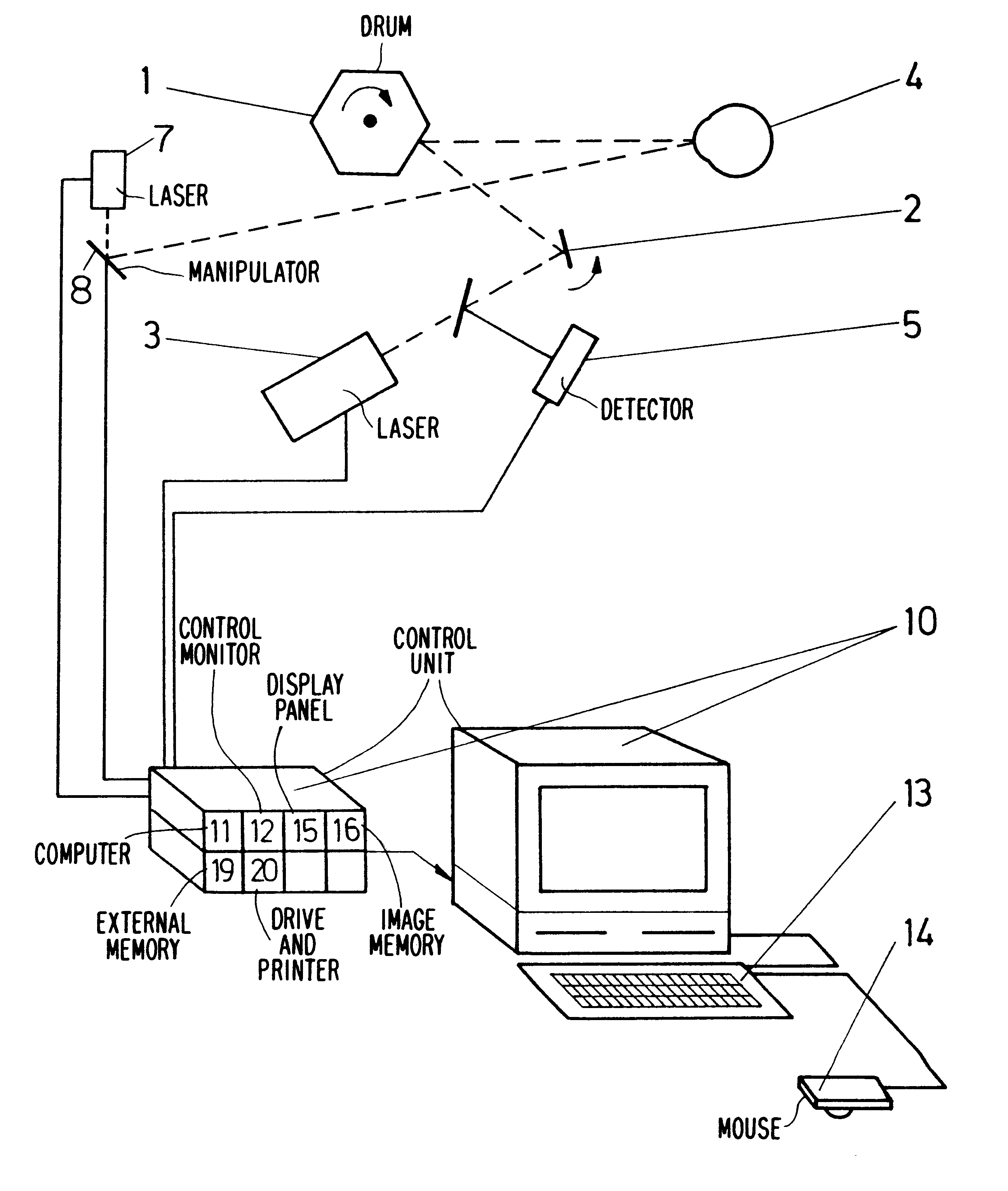
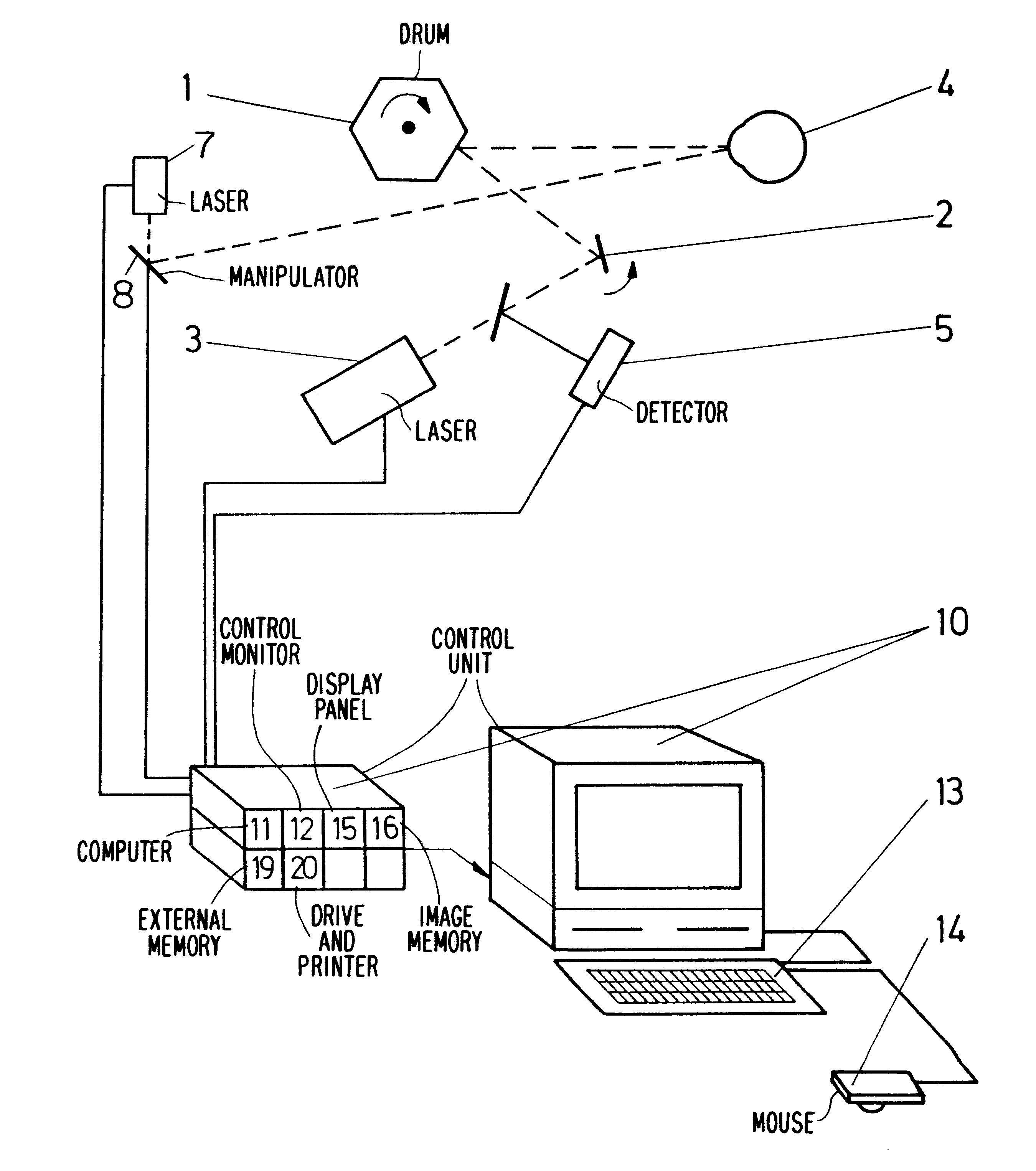
The present apparatus is provided in a prior art manner with a laser scanning ophthalmoscope having a scanning device, which preferably is composed of an x,y-scanner with a polygon mirror drum (1) and a galvanometer mirror (2) as such a system operates independently of wavelengths, which is an advantage when light of several wavelengths is employed simultaneously.

The scanning device directs the beam of a laser (3) to an eye (4), which is to be examined and treated, in such a manner that the laser beam scans the area to be treated. The light reflected by the eye is directed via the scanning device to a detector device (5), whose time sequential output signals are fed synchronically to the scanning movement by an electronic control and evaluation unit of prior art construction, to a video monitor on which in this manner a visual representation of the eye becomes visible.

The control unit (10), which is only depicted schematically, is provided with a computer (11) suitable for image pro...


PUM


Abstract

An apparatus for the observation and treatment of the eye with a laser, having an illumination light source, whose light is focussed on the part of the eye to be observed and which preferably contains a laser, a scanning device, which generates a scanning movement of the light of the illumination light source on the background of the eye, a detector device, which receives the reflected light, an evaluation and synchronization unit, which generates from the time-sequential signal output of the detector device a visual representation of the portions of the eye to be treated and shows the visual representation, on a monitor, and a treatment laser device, whose light can be reflected on the part of the eye to be treated. The apparatus provides that a visual representation in which the location or locations to be treated are marked, can be superimposed on the visual representation of the eye at least on the monitor, and a control unit aligns the laser to the marked location.

Description

The present invention relates to an apparatus for the observation and the treatment of the eye using a laser.State of the ArtBy way of illustration, the observation of the rear portion of the eye poses the problem that the illumination and the observation must be conducted through the pupil of the eye and the often optically turbid front eye mediae, where reflexes occur and which cause aberration errors.For this reason, it has often been suggested not to illuminate large areas of the background of the eye, but to scan as small as possible a spot with a focussed light and to detect the reflected light in ratio to the scanning sequence. In this connection, reference is made, by way of illustration, to "The Foundations of Ophthalmology", vol. VII, p. 307, 308, 1962, the U.S. Pat. No. 4,213,678 and the Japanese Patent Publications 61-5730 and 50-138822.The apparatuses known from the above-cited references differ, e.g. in pupil separation: a "GULLSTRAND pupil" is suggested in the Japanes...

Claims


Application Information

Patent Timeline
IPC IPC(8): A61B3/12A61F9/007A61F9/008A61B17/00
CPCA61B3/1225A61F9/008A61B2017/00694A61F2009/00897A61F2009/00846
Inventor FEUERSTEIN, MANFREDKLINGBEIL, ULRICHLANGOSCH, HERBERTREIS, WERNERWILMS, KARL-HEINZEISENTRAGER, WOLFGANGBISLE, WERNERPLESCH, ANDREAS
Owner HEIDELBERG ENG
Why Eureka
Try Eureka