Interferometric device for recording the depth optical reflection and/or transmission characteristics of an object

an optical reflection and transmission characteristic technology, applied in the field of optical tomography acquisition of images, can solve the problems of exacerbated one-dimensional measurement disadvantages in terms of measurement time and susceptibility to movement of objects, and serious disruptions

Inactive Publication Date: 2001-07-31
CSEM CENT SUISSE DELECTRONIQUE & DE MICROTECHNIQUE SA RECH & DEV
View PDF7 Cites 85 Cited by
  • Summary
  • Abstract
  • Description
  • Claims
  • Application Information

AI Technical Summary

Problems solved by technology

Such a scanning-based measurement process involving several measurements spaced out over time presents certain disadvantages, because, in addition to the fact that the measurement is necessarily fairly lengthy, it is seriously disrupted if the object is subject to movements.
Furthermore, to move the mirror, it is necessary to use a mechanical movement element, which can result in vibrations and, possibly, a drop in perform

Method used


Image

  • Interferometric device for recording the depth optical reflection and/or transmission characteristics of an object
  • Interferometric device for recording the depth optical reflection and/or transmission characteristics of an object
  • Interferometric device for recording the depth optical reflection and/or transmission characteristics of an object

Examples


Embodiment Construction

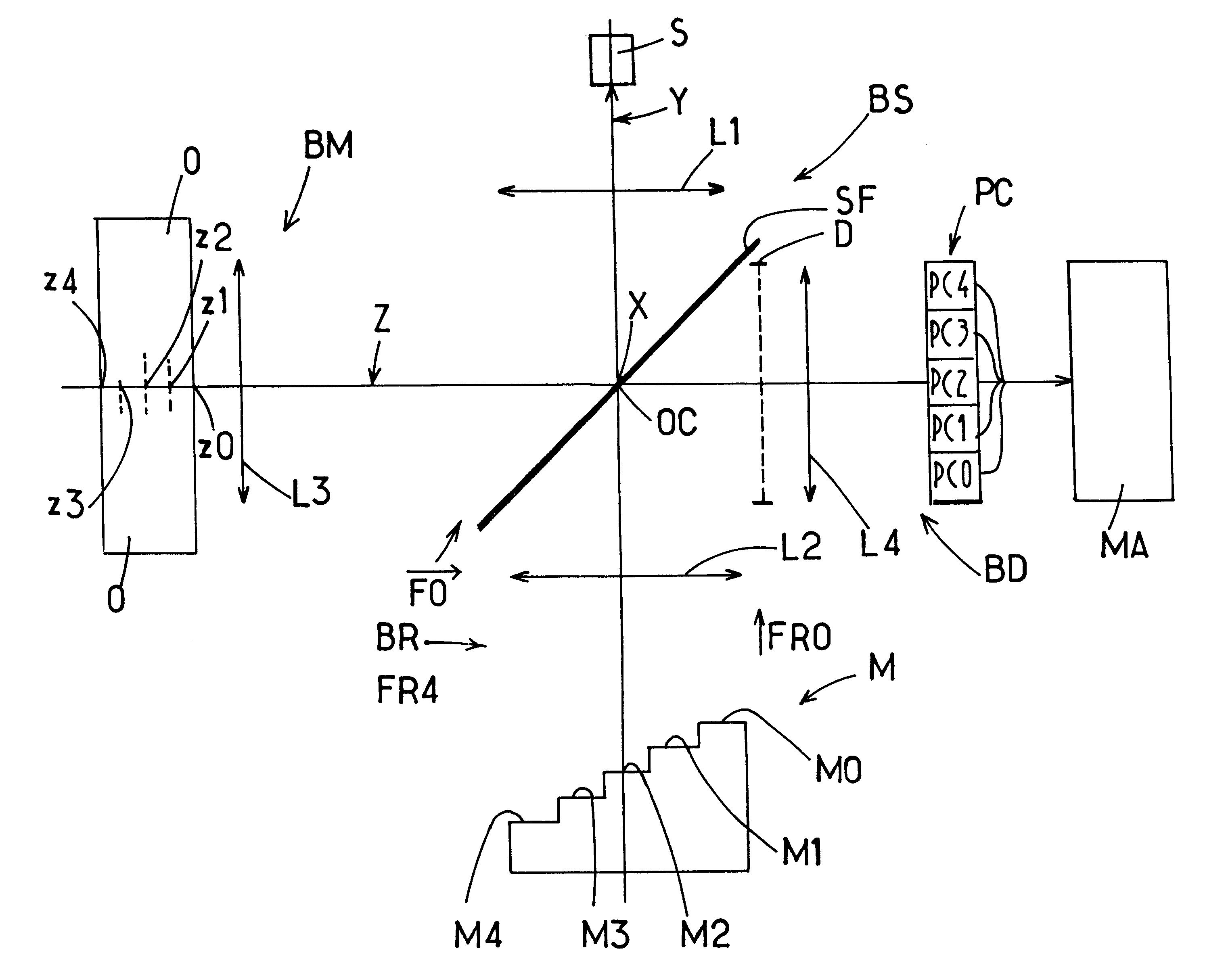
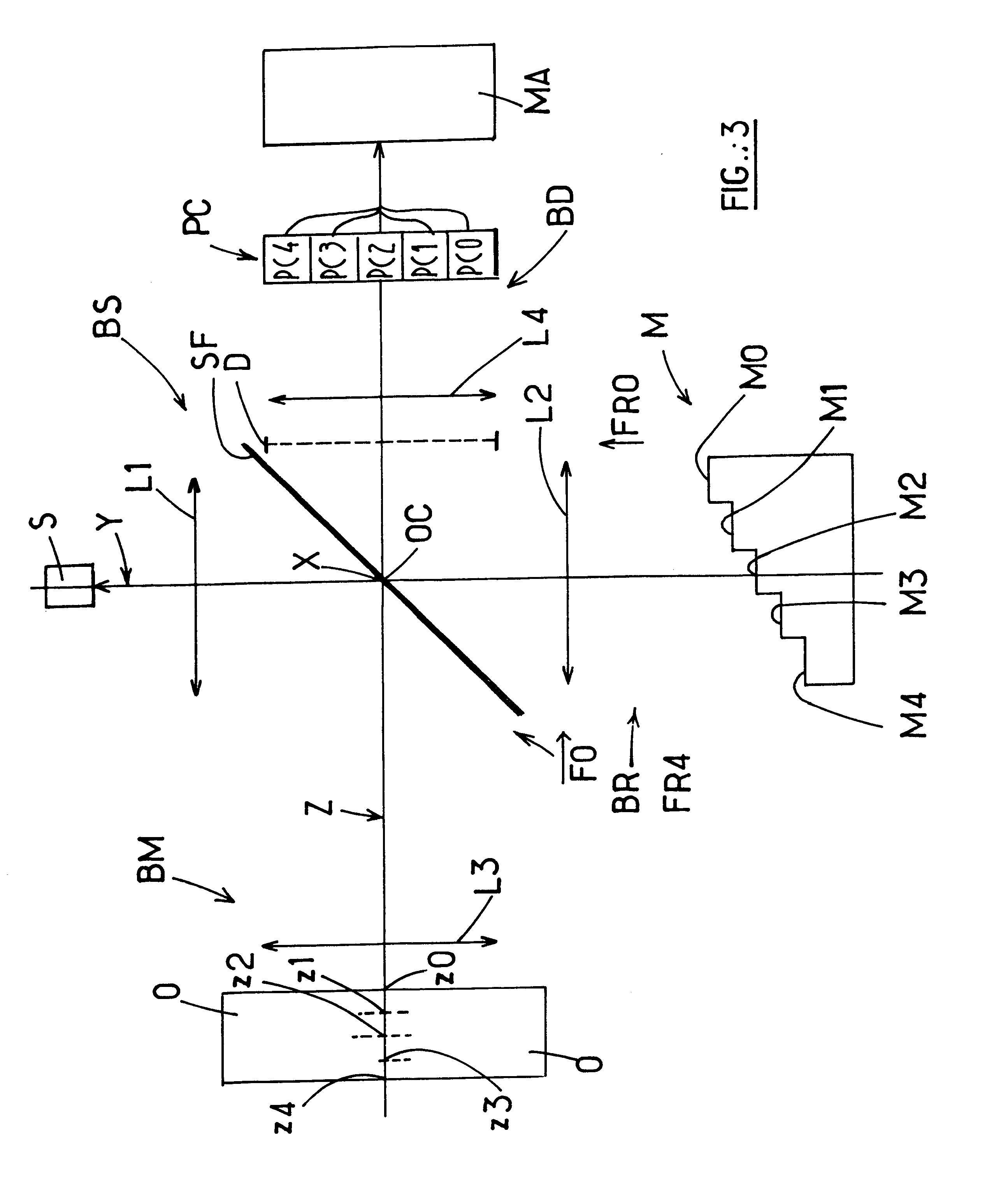
The description now refers to FIGS. 3, 3A and 3B, which represent a typical embodiment of an interferometric system according to the invention which can be used to record the depth reflection characteristics of an object O. In this example, the system is said to be "one-dimensional" because it can record measurement data only on a single axis Z which is assumed to pass through the object. In other words, in the example, the measurement data are taken at five points z0 to z4, point z0 being located, for example, at the front, and point z4 at the back of the object. Intermediate points z1, z2 and z3 can be representative of other places in the object where the reflection characteristics can translate its structural properties, for example. The readings from the measurements taken can then inform the observer as to the typical characteristics of the object.

The number of measurement points is by way of indication only, since the system can simultaneously record many more points at a tim...


PUM


Abstract

A tomographic interferometer device in which a spectral light source lights an object to create an object beam originating from that object. A stepped optical block is also exposed to the source to create a plurality of individual reference beams having different path lengths. The object beam and reference beams are made to interfere and the resulting light is sent to an array of side by side photodetectors. A plurality of lenses steer the light generated by the interference of each of the individual reference beams with the object beam to different photodetector cells of the array for generating a tomographic image of the object

Description

1. Field of the InventionThe present invention relates to the acquisition of images by optical tomography, whereby it is possible to obtain images formed by light ray intensities originating from an object to be studied, these intensities being a function of the depth in that object. These optical intensities can be obtained either by the reflection of rays on or in the object, or by the transmission of light through said object.More particularly, the invention concerns the area of optical low-coherence interferometry and applies the principle of the Michelson interferometer.FIG. 1 in the appended drawings represents such an interferometer. It includes a light source S with a broad spectral bandwidth which consequently has a low coherence length. The beam from this source is steered to a beam splitter SF which splits the beam from the source into a beam lighting an object O to be studied and a beam striking a reference mirror M.In this figure, the beam striking the object O and the ...

Claims


Application Information

Patent Timeline
IPC IPC(8): G01B9/02G01B11/24G01B11/02G01B11/22
CPCG01B11/026G01B11/22G01B11/2441G01B9/02028G01B9/0209G01B9/0201G01B2290/45
Inventor SEITZ, PETERBOURQUIN, STEPHANESALATHE, RENE-PAUL
Owner CSEM CENT SUISSE DELECTRONIQUE & DE MICROTECHNIQUE SA RECH & DEV
Why Eureka
Try Eureka