CSI based drive having feedforward control of inverter input voltage

a technology of inverter input voltage and csi based drive, which is applied in the direction of circuit arrangement, power conversion system, electric power transfer ac network, etc., can solve the problems of difficult to accurately measure the system impedance, difficult to stabilize the system, and worse situation

Inactive Publication Date: 2001-07-31
ALLEN-BRADLEY CO LLC
View PDF2 Cites 74 Cited by
  • Summary
  • Abstract
  • Description
  • Claims
  • Application Information

AI Technical Summary

Problems solved by technology

This makes it difficult to stabilize the system if the drive operates at a frequency which is close to the resonant frequency.
The situation becomes even worse when the motor is unloaded since the inverter output current in this case is minimal whereas the resonant current flowing between the capacitor and the motor magnetizing inductance is substantial.
A similar resonance problem also exists when a PWM rectifier is employed in the drive to provide direct current to the CSI from a power source.
Unfortunately it is difficult to measure the system impedance accurately, which complicates the design of a compensating filter.
In addition, even when the resonance frequency is not close to any characteristic harmonic of the rectifier, undesired oscillations will also occur during transient states.
Otherwise an interaction between the motors and inverter will occur when one or more motors are loaded or unloaded, making the system unstable.

Method used


Image

  • CSI based drive having feedforward control of inverter input voltage
  • CSI based drive having feedforward control of inverter input voltage
  • CSI based drive having feedforward control of inverter input voltage

Examples


Embodiment Construction

The detailed description is divided into two parts. The first portion of the discussion relates to active damping control in order to suppress resonance modes. The second part of the discussion centres on enhancement of the CSI-based drive through the use of feedforward control.

1. Active Damping Control

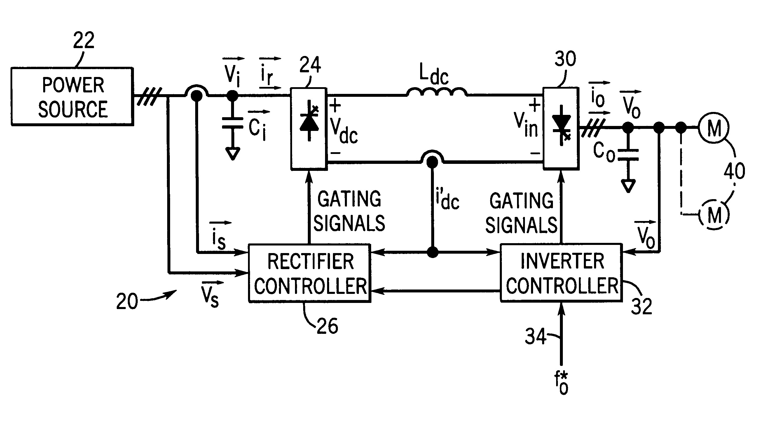
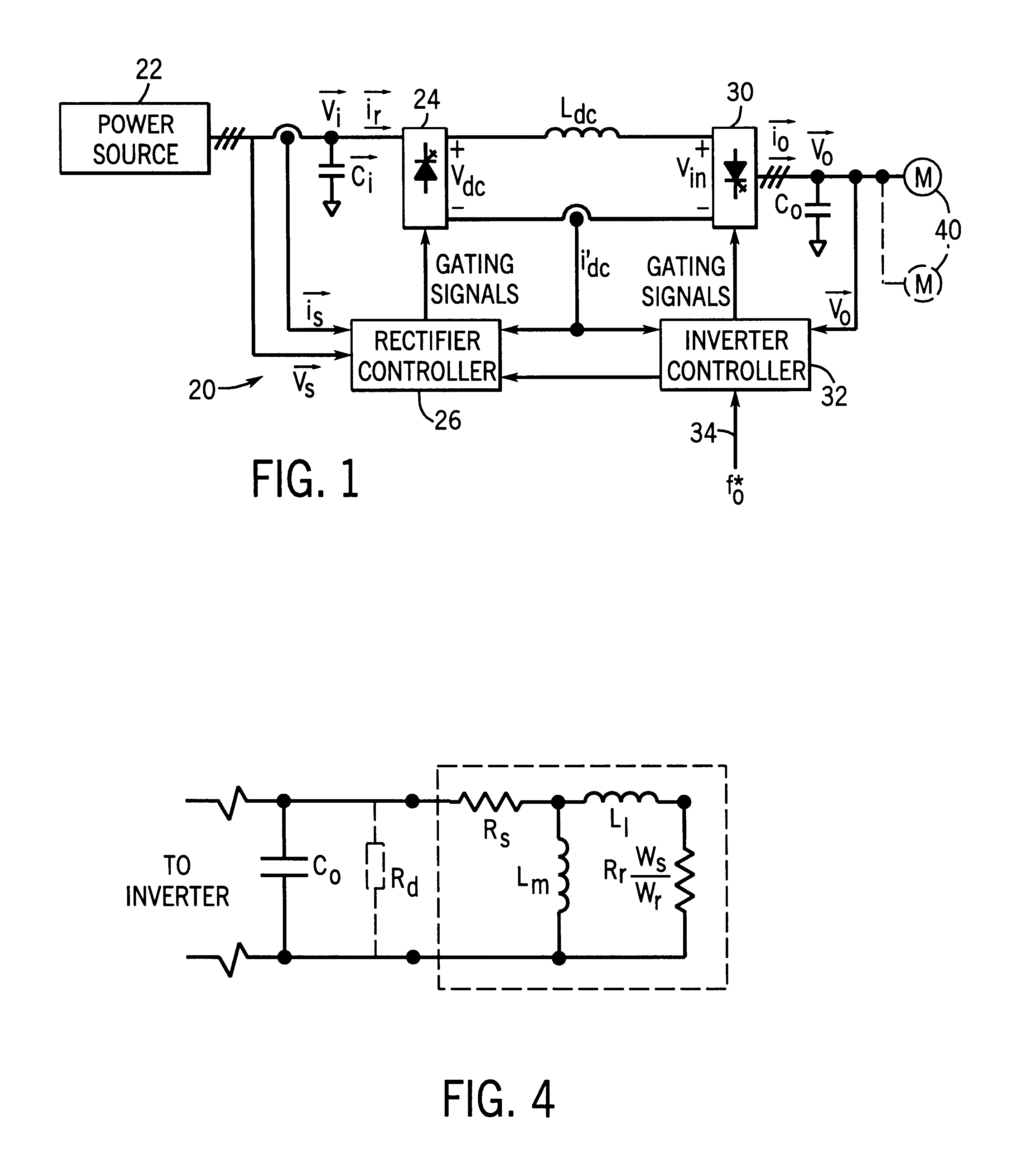
Referring to the drawings, FIG. 1 shows a schematic block diagram of a drive 20 for control of one or more a.c. induction motors 40. The drive 20 comprises a rectifier 24 coupled to a current source inverter 30 via a d.c. link choke or inductor L.sub.dc. The rectifier 24 converts alternating current supplied from a three-phase power source 22 into direct current which is smoothed by the d.c. link choke L.sub.dc, thereby providing a current source for the inverter 30. The inverter 30, in turn, converts the d.c. current into a three-phase alternating current (which may vary in terms of its frequency as well as magnitude) for supply to the a.c. induction motor 40.

The current source inver...


PUM


Abstract

The drive for an a.c. induction motor features a rectifier for converting alternating current into direct current and a current source inverter for converting direct current into alternating current supplied to a motor. A d.c. link choke interconnects the rectifier and the inverter. The inverter includes a first control loop which provides a desired or command d.c. link choke current to a second control loop responsible for the rectifier. For the purposes of the second control loop the actual d.c. link choke current and an input voltage of the inverter are detected. The difference or error between the desired and actual d.c. choke currents are minimized by a compensator. The output of the compensator is added to the detected inverter input voltage, and the sum is fed to a switching pattern generator which controls the switches in the rectifier. In this manner the feedback of the inverter input voltage is decoupled from the compensator responsible for the d.c. link choke current. This makes the parameters of the second control loop substantially independent of the load, thereby enhancing the ease with which the control loop may be tuned and hence the stability of the drive.

Description

The invention generally relates to the field of power electronics. Conjointly, the invention also relates to a drive for an alternating current (a.c.) induction motor which employs a current source inverter and features improved voltage regulation and suppressed resonance between the drive and motor. The improved drive is suitable for high power multi-motor applications.BACKGROUND OF INVENTIONPulse width modulated current source inverter (CSI) based a.c. motor drives are increasingly used in high power (e.g., 1,000.about.10,000 hp) applications. See, for instance, P. M. Espelage and J. M. Nowak, "Symmetrical GTO Current Source Inverter for Wide Speed Range Control of 2300 to 4160 volt, 350 to 7000 hp, Induction Motors", IEEE IAS Annual Meeting, pp 302.about.307, 1988. Compared with voltage source inverter fed drives, the CSI drive features simple structure, reliable short circuit protection, four quadrant operation capability and nearly sinusoidal output voltage and current waveform...

Claims


Application Information

Patent Timeline
Patent Type & Authority Patents(United States)
IPC IPC(8): H02M5/00H02M5/45
CPCH02M5/4505H02M2001/0022H02M1/0022
Inventor MA, DAMINGWU, BINZARGARI, NAVID R.RIZZO, STEVEN C.
Owner ALLEN-BRADLEY CO LLC
Why Eureka
Try Eureka