Method and arrangement for demodulating data symbols

a data symbol and data arrangement technology, applied in the field of method and arrangement for demodulating data symbols, can solve the problems of neither teaching nor suggesting an actual combination, and none of the documents suggests a combination of the information derived

Inactive Publication Date: 2001-07-31
TELEFON AB LM ERICSSON (PUBL)
View PDF9 Cites 35 Cited by
  • Summary
  • Abstract
  • Description
  • Claims
  • Application Information

AI Technical Summary

Benefits of technology

The invention, on average, provides demodulation of a received data signal at a quality level, that is superior to what may be accomplished by a corresponding demodulator, which for every received burst, selects the optimal demodulation direction for the signal samples contained therein.
According to the present invention, the influence of error propagation, due to erroneously received signal samples or erroneously demodulated data symbols, is also minimised.
The demodulated signal quality, which is gained through use of the invention, can be taken advantage of in various ways. For instance, given a particular quality level, the complexity of the demodulator can be lowered. Consequently, without lowering the standards of quality, cheaper, simpler and / or less power consuming demodulation devices may be applied any receiver of digital-data-modulated symbols, such as a radio base station or a mobile terminal.
If instead, the demodulator is fixed, the invention provides a higher data symbol quality than any of the previously known solutions does.
The invention moreover offers very flexible digital demodulation solutions, because it is applicable to any kind of sequentially operating demodulator / equaliser, such as e.g. LE:s (LE=Linear Equaliser), DFE:s, DFSE:s (DFSE=Decision Feedback Sequence Estimation) and RSSE:s (RSSE=Reduced State Sequence Estimation).

Problems solved by technology

However, none of the documents suggests a combination of the information derived from the two demodulation directions.
However, the paper neither teaches nor suggests an actual combination of the results from two independent demodulations of the same signal samples, performed in opposite directions.

Method used


Image

  • Method and arrangement for demodulating data symbols
  • Method and arrangement for demodulating data symbols
  • Method and arrangement for demodulating data symbols

Examples


Embodiment Construction

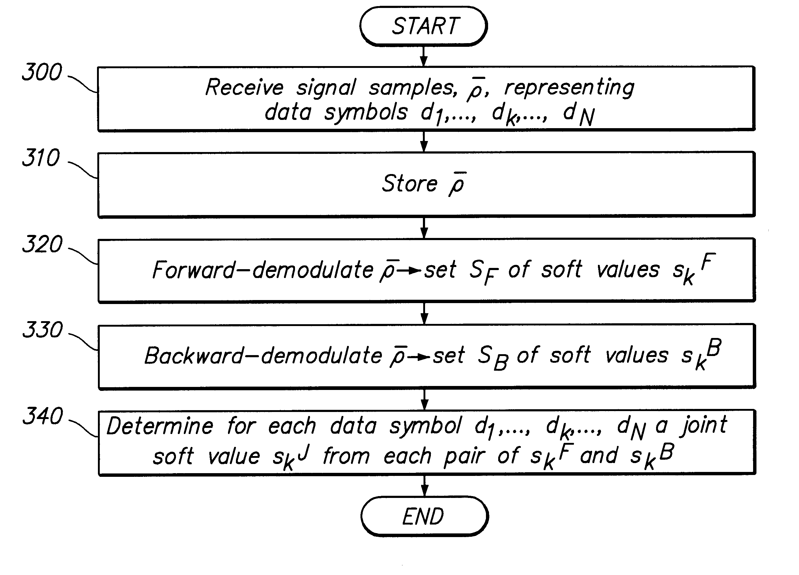
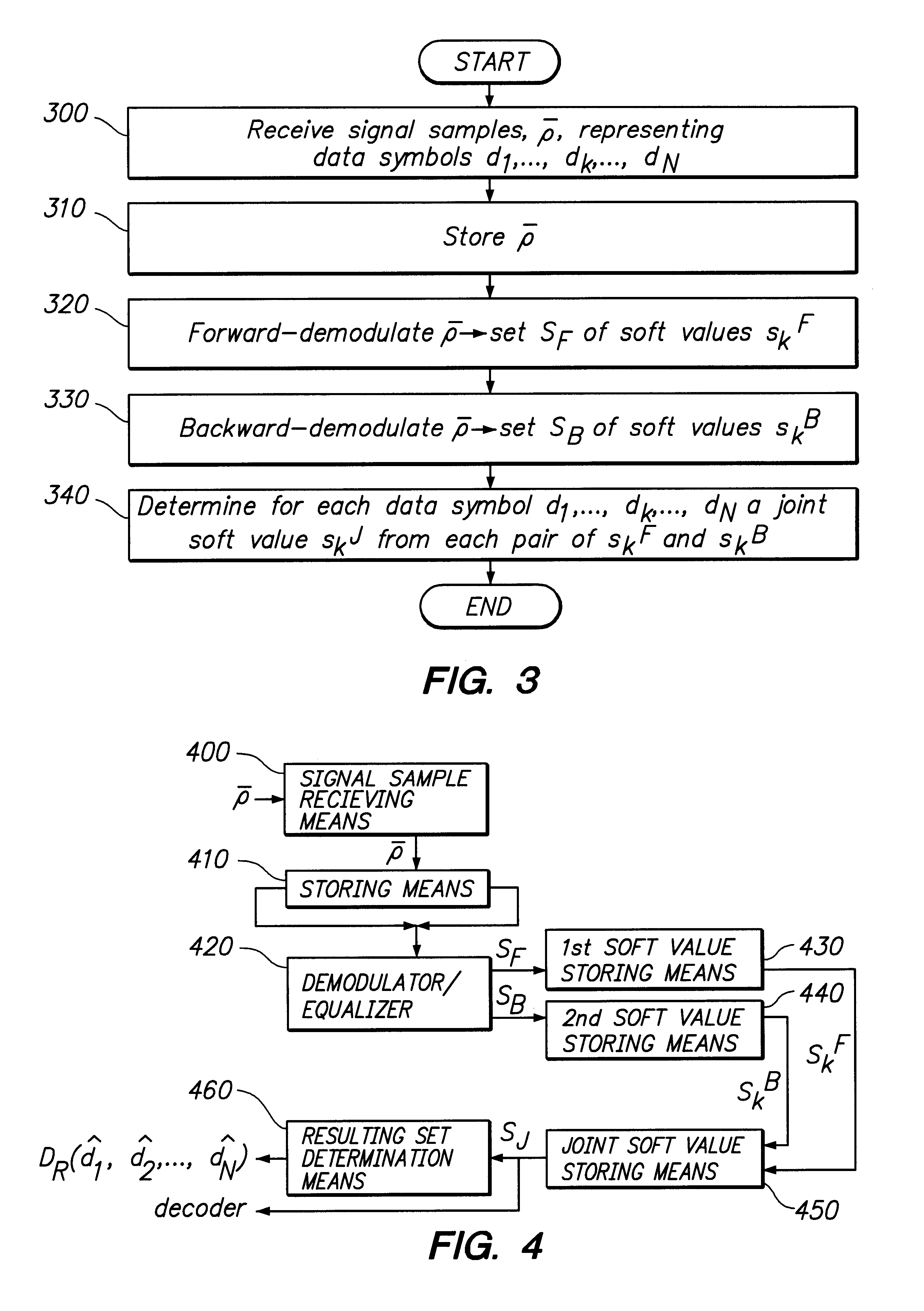
In FIG. 3 is depicted a flow diagram over the method according to the invention. Signal samples p, representing data symbols d.sub.1, . . . , d.sub.k, . . . , d.sub.N, which have been received over a particular communication channel are collected in a first step 300 and stored in a second step 310. Typically but not necessary, the number of signal samples .rho. is a multiple of the number of data symbols N, i.e. the number of elements in the vector .rho. equals x.multidot.N, where x is a positive integer. The number of signal samples .rho. is in any case at least greater than or equal to the number of data symbols N. In a subsequent step 320, the signal samples .rho. are demodulated in the forward direction, through a demodulator / equaliser. As a result is obtained, a first set S.sub.F of soft values s.sub.k.sup.F, which each is associated with a particular data symbol d.sub.k. The soft value s.sub.k.sup.F is a vector, whose elements are probability functions, that for each data symb...


PUM


Abstract

The present invention relates to a method and an arrangement for demodulating data symbols (d1-dN) having been transmitted through a communication channel, particularly a channel suffering from one or more impairments. Received signal samples ({overscore (rho)}), representing the sent data symbols (d1-dN), are stored (310) and demodulated in both the forward (320) and the backward direction (330), via a demodulator / equaliser. In course of the demodulations are produced a first (SF) and a second (SB) respective set of soft values (skF; skB), which each is associated with a certain data symbol (dk). (340) From every pair of soft values (skF; skB) is then determined a joint soft value (SkJ), which e.g. may be utilised for deriving a resulting set of data symbols ({circumflex over (d)}1-{circumflex over (d)}N) or for directly decoding the payload information contained in the data symbols (d1-dN).

Description

This application claims priority under 35 U.S.C. .sctn..sctn.119 and / or 365 to 9703389-8 filed in Sweden on Sep. 19, 1997; the entire content of which is hereby incorporated by reference.The present invention relates to a method for demodulating data symbols having been transmitted through a communication channel, particularly a channel suffering from one or more impairments, such as frequency selective fading, inter symbol interference and distortion, which may be temporally constant or time-varying.The invention also relates to an arrangement for carrying out the method.DESCRIPTION OF THE PRIOR ARTWhen digital-data-modulated signals are to be transmitted over a rapidly fading communication channel, such as a radio channel in a mobile radio communications system, a commonly used technique to cope with the changing channel is to include a predetermined data symbol sequence in the transmitted signal at suitably frequent intervals. The known symbol sequence is used in a receiver by a ...

Claims


Application Information

Patent Timeline
Patent Type & Authority Patents(United States)
IPC IPC(8): H04L25/03
CPCH04L25/03038H04L2025/0356
Inventor JAVERBRING, STEFANHOOK, MIKAEL
Owner TELEFON AB LM ERICSSON (PUBL)
Why Eureka
Try Eureka