Tubular fitting, tool and method

Inactive Publication Date: 2001-08-07
SPERKO WALTER J
View PDF15 Cites 9 Cited by
  • Summary
  • Abstract
  • Description
  • Claims
  • Application Information

AI Technical Summary

Benefits of technology

It is therefore an objective of the invention to provide a method of reconditioning c

Problems solved by technology

However, brazing is more expensive, from both a materials and time stand point, and higher operating temperatures are required.
Thus standard

Method used


Image

  • Tubular fitting, tool and method
  • Tubular fitting, tool and method
  • Tubular fitting, tool and method

Examples


Embodiment Construction

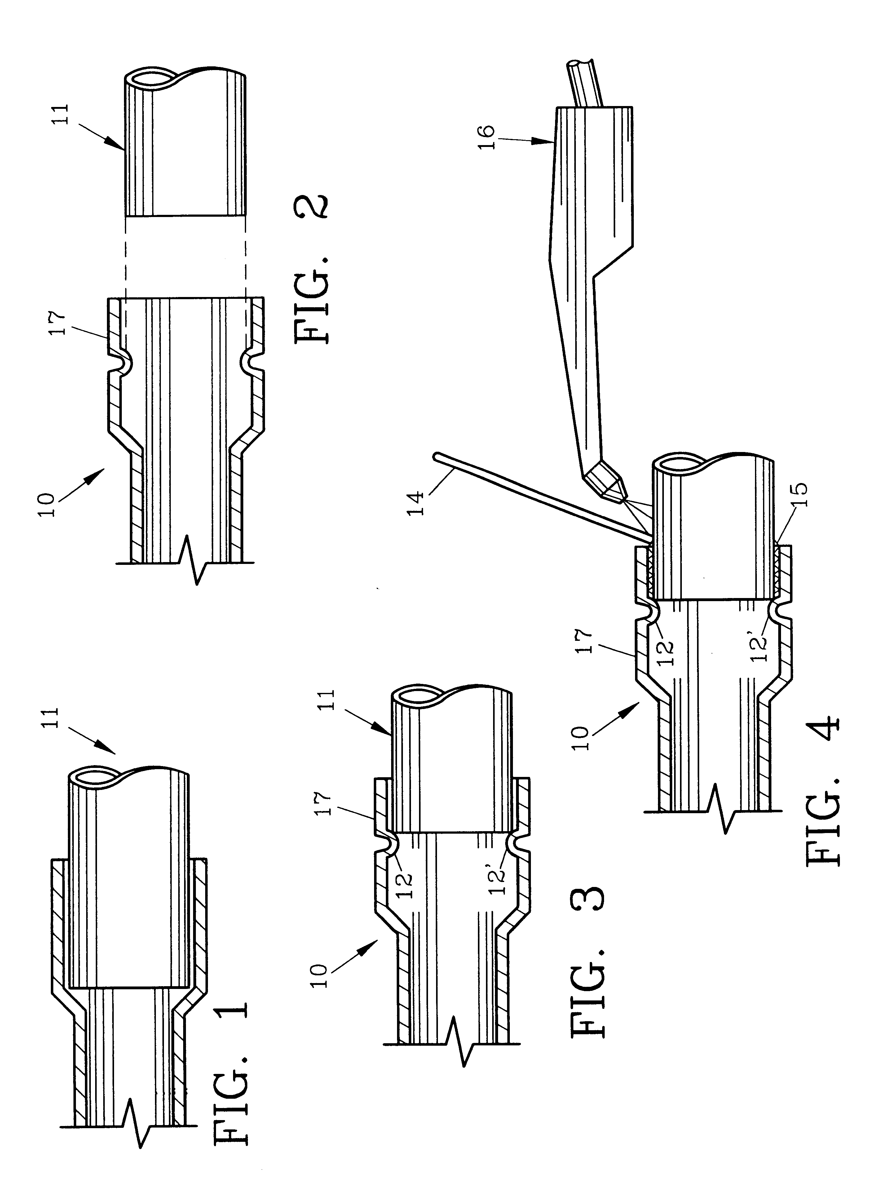
For a better understanding of the invention and its operation, turning now to the drawings, FIG. 2 shows a partial view of a preferred reconditioned socket fitting of the invention in cross-sectional view prior to insertion of tubular member 11 which may be for example, a copper pipe which is dimensioned for reception by socket 17. As seen in FIG. 3, tubular member 11 has been inserted into socket 17 and abuts ridges 12, 12' formed therein. Ridges 12, 12' preferably are dimples pressed into socket 17 as will be hereinafter described in more detail.

Once tubular member 11 has been fully inserted into socket 17 which as shown in FIGS. 3 and 4 is about one-half of the normal socket length, metal adherent 15 such as a conventional brazing metal composition is applied as usual between tubular member 11 and the inner walls of socket 17 to rigidly connect tubular member 11 and socket fitting 10 (FIG. 4). Heat to melt and flow adherent 15 is supplied utilizing a conventional brazing rod 14 a...


PUM

PropertyMeasurementUnit
Fractionaaaaaaaaaa
Fractionaaaaaaaaaa
Fractionaaaaaaaaaa

Abstract

A method and tools for forming ridges or dimples in tubular members such as copper pipes is provided. A manual tool has a pair of jaws which can be adjustably positioned and has a threaded ram affixed to one of the jaws for rotation. The jaws are adjustable for holding various thicknesses of pipe walls in firm engagement as the ram is manually rotated to form a ridge in the pipe wall. A hydraulic tool is also described for high production requirements.

Description

The invention herein pertains to tubular fittings, connections and tools used therefor and specifically concerns reconditioning copper fittings as are used in potable water, heating and air conditioning systems to effectively shorten the socket length.BACKGROUND AND OBJECTIVES OF THE INVENTIONTubes or pipes formed from copper have been the preferred type for homeowners, engineers and architects for many years due to the availability, durability and convenience in assembly. Copper tubing ranging from about one-quarter inch (0.63 cm) to six inches (15.24 cm) are commercially available along with copper socket fittings such as elbows, T's, connectors and the like. Tubes and fittings are normally joined by soldering by first inserting the tube into the fitting socket and then by heating the tube and fitting to a sufficient temperature (approximately 450.degree. F.; 232.degree. C.) to allow the tin based solder to flow into the fitting to provide a watertight joint once the solder harden...

Claims


Application Information

Patent Timeline
IPC IPC(8): B21D1/00B21D1/08B21D17/02B21D17/00B25B7/00B25B7/02
CPCB21D1/08B25B7/02B21D17/025
Inventor SPERKO, WALTER J.
Owner SPERKO WALTER J
Why Eureka
Try Eureka