Perpendicular magnetic recording medium

a magnetic recording medium and perpendicular technology, applied in the field of perpendicular magnetic recording medium, can solve the problems of soft magnetic layer or back layer having a domain wall, coercive force almost exceeding the recording ability of a record head, and inability to achieve high planar recording density with the predominant longitudinal recording system, etc., to achieve the effect of reducing or canceling the recorded magnetization and avoiding spike nois

Inactive Publication Date: 2001-08-07
WD MEDIA SINGAPORE PTE
View PDF8 Cites 96 Cited by
  • Summary
  • Abstract
  • Description
  • Claims
  • Application Information

AI Technical Summary

Benefits of technology

It is therefore an object of the present invention to provide a new and useful perpendicular magnetic recording medium exhibiting a desirable envelope characteristic at the time of recording and reproduction and free from spike noise and the decrease or cancellation of recorded magnetization ascribable to the movement of the domain wall of a soft magnetic layer or back layer.

Problems solved by technology

However, high planar recording density is not achievable with the predominant longitudinal recording system without bringing about the thermal jitter of recorded magnetization ascribable to a decrease in the size of bits.
In addition, a coercive force almost exceeding the recording ability of a record head is required.
However, a problem with the above conventional medium is that the soft magnetic layer or back layer has a domain wall (magnetic domain) structure, e.g., either a Bloch domain wall or a Neil domain wall.
The domain wall produces spike noise at the time of recording and reproduction of data from the medium.
Spike noise degrades the envelope characteristic of the medium and thereby obstructs faithful reproduction.
This kind of noise occurs when a head moves above the domain wall of the soft magnetic film.
Another problem is that the recorded magnetization of the medium is unstable due to external stray magnetic fields.
Although such magnetic fields are extremely weak, they cause the domain wall of the soft magnetic film to move when concentrating on the tip of the main pole of the head, reducing or even canceling the recorded magnetization.
This is a critical defect when it comes to a data storing apparatus.

Method used


Image

  • Perpendicular magnetic recording medium
  • Perpendicular magnetic recording medium
  • Perpendicular magnetic recording medium

Examples


first embodiment

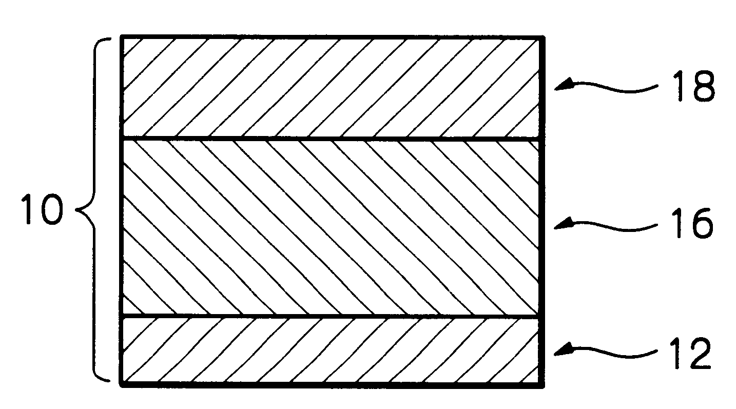
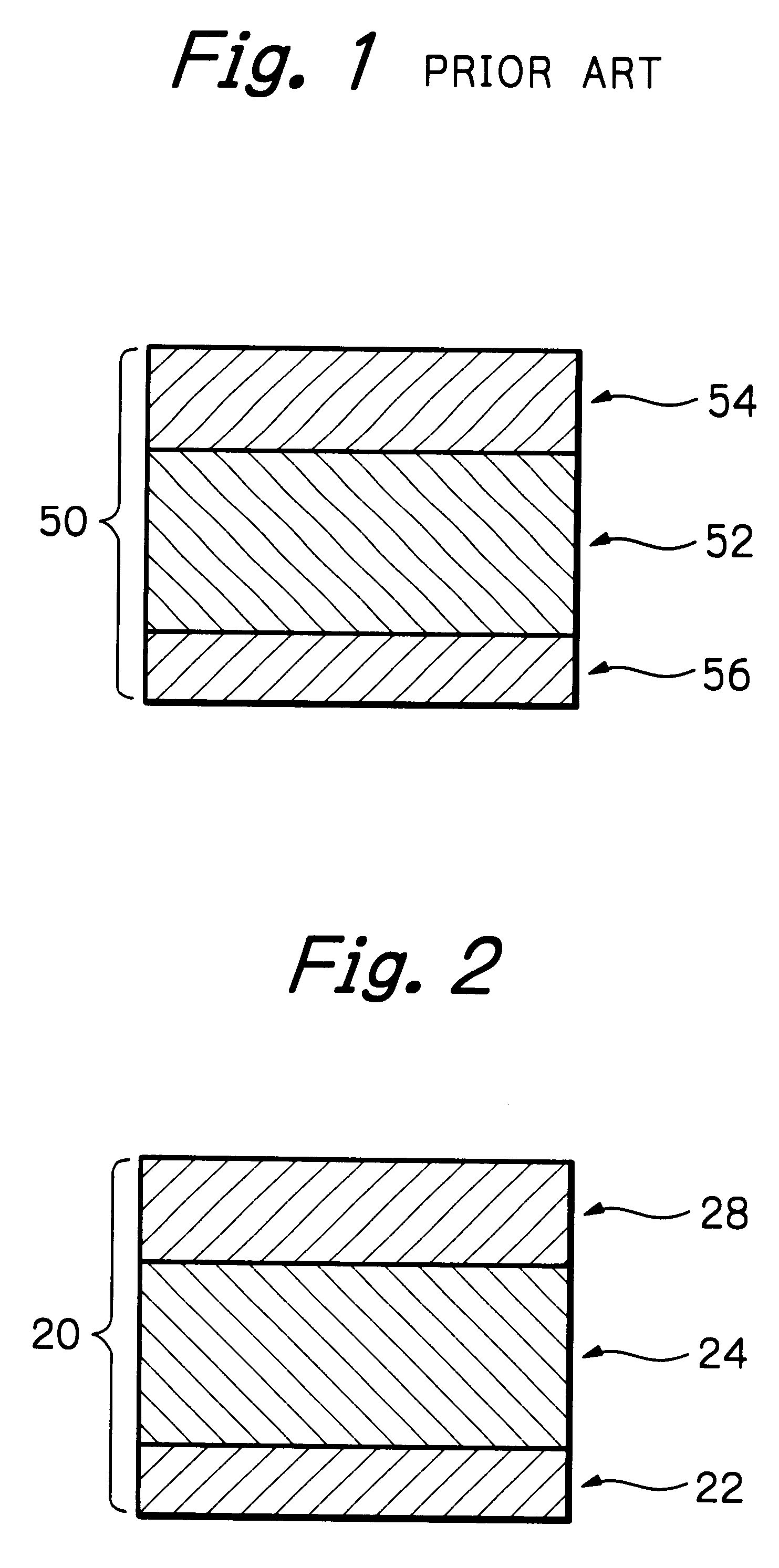
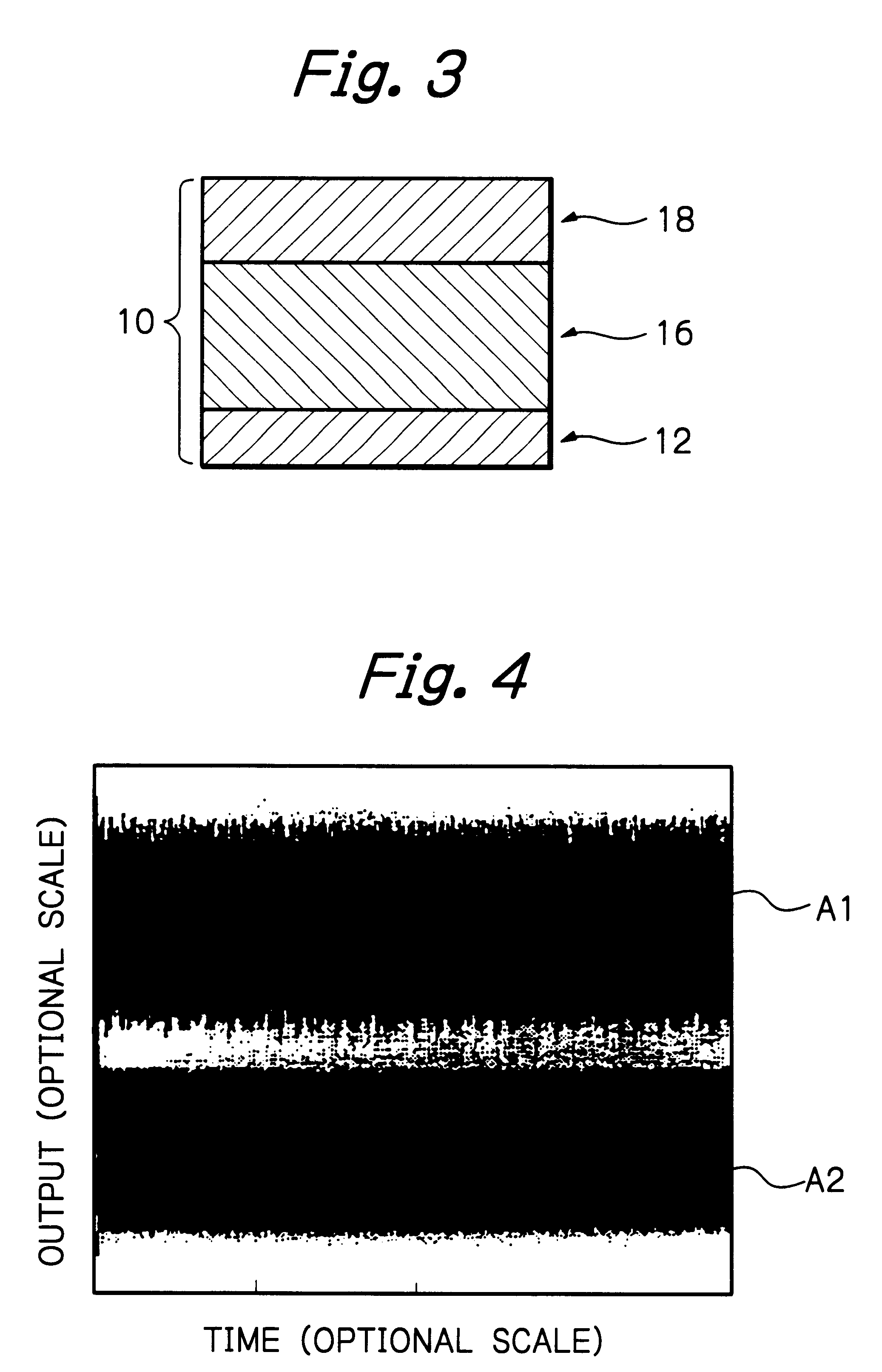
Referring to FIG. 3, a first embodiment of the perpendicular magnetic recording medium in accordance with the present invention is shown and generally designated by the reference numeral 10. As shown, the recording medium 10 includes a 2.5 inch thick substrate 12. A 500 nm thick soft magnetic film or back layer 16 is formed on the substrate 12 and formed of FeSiAl. A perpendicular magnetization film 18 is formed on the soft magnetic film 16 and formed of Co.sub.78 Cr.sub.19 Ta.sub.3 (at %). The recording medium 10 additionally includes a C protection layer not shown.

A procedure for producing the above recording medium 10 is as follows. First, by using a 6 inch thick FeSiAl target, the soft magnetic film 16 in the form of a 500 nm thick FeSiAl film was formed on the 2.5 inch substrate 12 by sputtering under the following conditions:

Initial chamber vacuum: below 5.times.10-7 mTorr

Substrate Temperature: 600.degree. C.

Power: 0.5 kW

Argon gas pressure: 4 mTorr

Film forming rate: 3 nm / sec

Su...

second embodiment

A perpendicular magnetic recording medium B2 was produced that was identical with the medium A2 except that an FeSiAlRuTi film target was used in order to form an FeSiAlRuTi film on a substrate as a soft magnetic film. For the comparison of coercive forces, another FeSiAlRuTi film was formed at a substrate temperature held at room temperature. The FeSiAlRuTi film of the medium B2 showed no clear domain wall structure and showed no change even when a magnetic field was applied thereto little by little. This was also true with the FeSiAlRuTi film formed at room temperature. This proves that the magnetization of the FeSiAlRuTi film is not derived from the movement of a domain wall.

The coercive force of the medium B2 was measured to be 0.1 Oe. The FeSiAlRuTi film formed at room temperature had a coercive force of 300 Oe. As for the recording and reproducing characteristics, the medium B2, like the medium A2 had a far sharper envelope than the conventional medium A1. Such a difference in...

third embodiment

A perpendicular magnetic recording medium Q2 was produced that was identical with the medium A2 except that an FeTaN film target was used in order to form an FeTaN film on a substrate as a soft magnetic film. For the comparison of coercive forces, another FeTaN film was formed at a substrate temperature held at room temperature. The FeTaN film of the medium Q2 showed no clear domain wall structure and showed no change even when a magnetic field was applied thereto little by little. This was also true with the FeTaN film formed at room temperature. This proves that the magnetization of the FeTaN film is not derived from the movement of a domain wall.

The coercive force of the medium Q2 was measured to be 0.1 Oe. The FeTaN film formed at room temperature had a coercive force of 300 Oe. As for the recording and reproducing characteristics, the medium Q2, like the medium A2 had a far sharper envelope than the conventional medium A1. Such a difference in envelope characteristic was also i...


PUM

PropertyMeasurementUnit
coercive forceaaaaaaaaaa
thicknessaaaaaaaaaa
thicknessaaaaaaaaaa

Abstract

In a perpendicular magnetic recording medium, a soft magnetic film playing the role of an back layer, but not having a domain wall structure, is positioned beneath a perpendicular magnetization film. Such a back layer improves the envelope characteristic of the medium at the time of recording and reproduction. Moreover, the medium is free from spike noise and the decrease or cancellation of recorded magnetization ascribable to the movement of the domain wall of a back layer. The medium of the present invention is therefore a drastic solution to the problems particular to a conventional perpendicular magnetic recording medium and realizes desirable recording and reproducing characteristics.

Description

BACKGROUND OF THE INVENTIONThe present invention relates to a perpendicular magnetic recording medium usable as, e.g., a magnetic disk and, more particularly, to a perpendicular magnetic recording medium having desirable recording and reproducing characteristics.In parallel with the advance of personal computers and work stations, hard disk drives are increasing in capacity and decreasing in size and needs magnetic disks capable of recording data in higher planar density. However, high planar recording density is not achievable with the predominant longitudinal recording system without bringing about the thermal jitter of recorded magnetization ascribable to a decrease in the size of bits. In addition, a coercive force almost exceeding the recording ability of a record head is required. Today, a perpendicular magnetic recording system is in study as an implementation for noticeably increasing planar recording density. For the perpendicular magnetic recording system, a double layer, ...

Claims


Application Information

Patent Timeline
Patent Type & Authority Patents(United States)
IPC IPC(8): G11B5/66G11B5/64G11B5/667G11B5/738
CPCG11B5/66Y10T428/265Y10S428/90
Inventor HOKKYO, HIROTAKATSUBOI, SHINZOTAGAMI, KATSUMICHI
Owner WD MEDIA SINGAPORE PTE
Why Eureka
Try Eureka