Device for conveying fuel from a reserve pot to the internal combustion engine of a motor vehicle

Inactive Publication Date: 2001-08-14
ROBERT BOSCH GMBH
View PDF11 Cites 33 Cited by
  • Summary
  • Abstract
  • Description
  • Claims
  • Application Information

AI Technical Summary

Problems solved by technology

However, this arrangement has the disadvantage of a complicated arrangement for closing the opening, which moreover requires a large amount of space.
In addition, such closing elements, which are located at the inlet to the mixing region, cannot close the opening tightly, so that especially when the engine

Method used


Image

  • Device for conveying fuel from a reserve pot to the internal combustion engine of a motor vehicle
  • Device for conveying fuel from a reserve pot to the internal combustion engine of a motor vehicle
  • Device for conveying fuel from a reserve pot to the internal combustion engine of a motor vehicle

Examples


Embodiment Construction

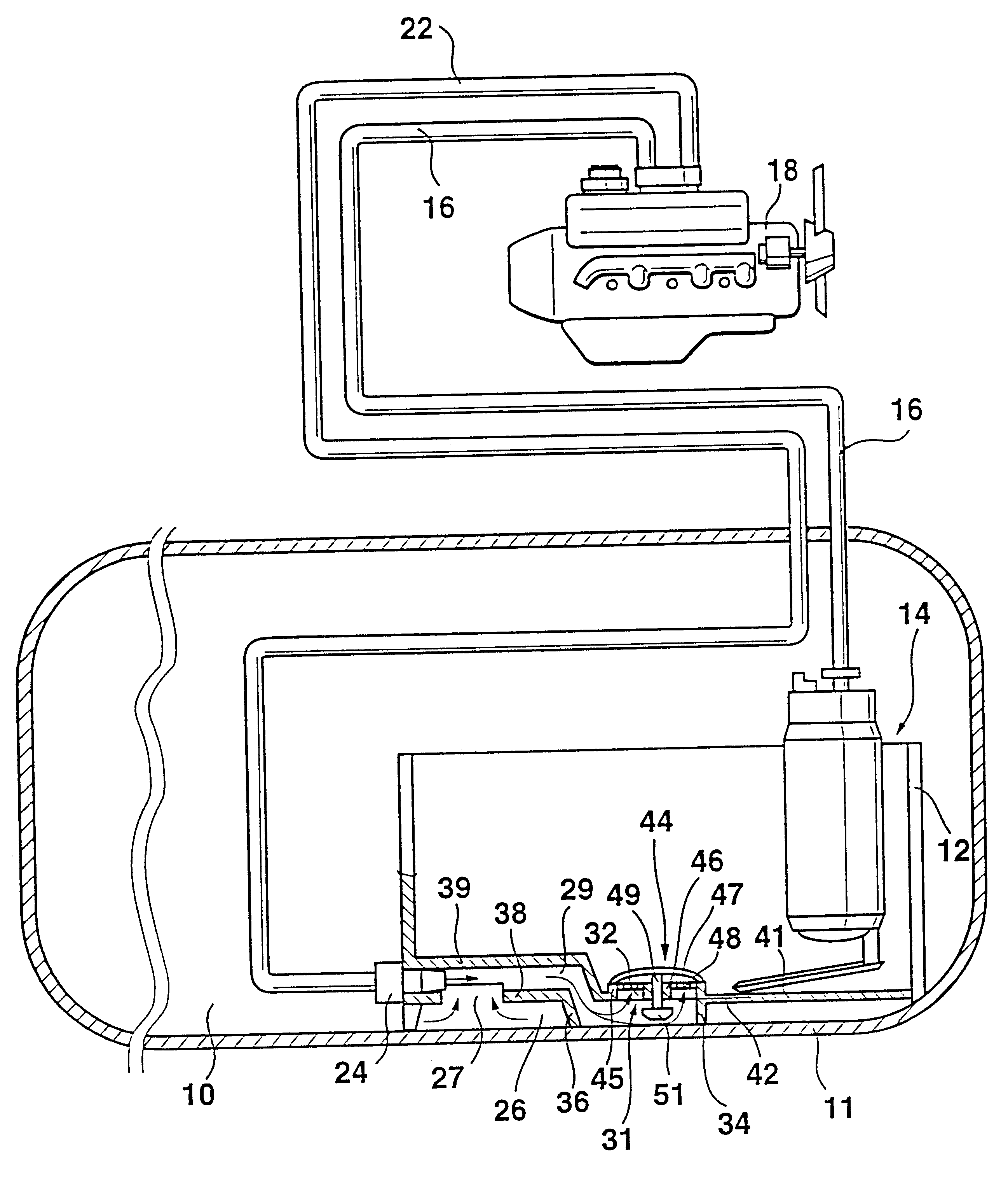
A device shown in FIG. 1 for conveying fuel has a fuel tank 10 in whose interior a separate container-like reserve pot 12 is accommodated. The separate reserve pot 12 is embodied in potlike form, and a conveying unit 14, which includes an electrical drive motor and a pump portion accommodated in a common housing, is disposed in this reserve pot 12. The conveying unit 14 aspirates fuel from the reserve pot 12 and forces it via a supply line 16 to the internal combustion engine 18 of a motor vehicle, not shown in detail. A check valve can be accommodated in the supply line 16. Since the conveying unit 14 furnishes more fuel for the engine 18 than the engine can use, a return line 22 carries the excess fuel back into the tank 10. Located at the end of the return line 22 is a jet pump 24, which carries the return-flowing fuel into the reserve pot 12.

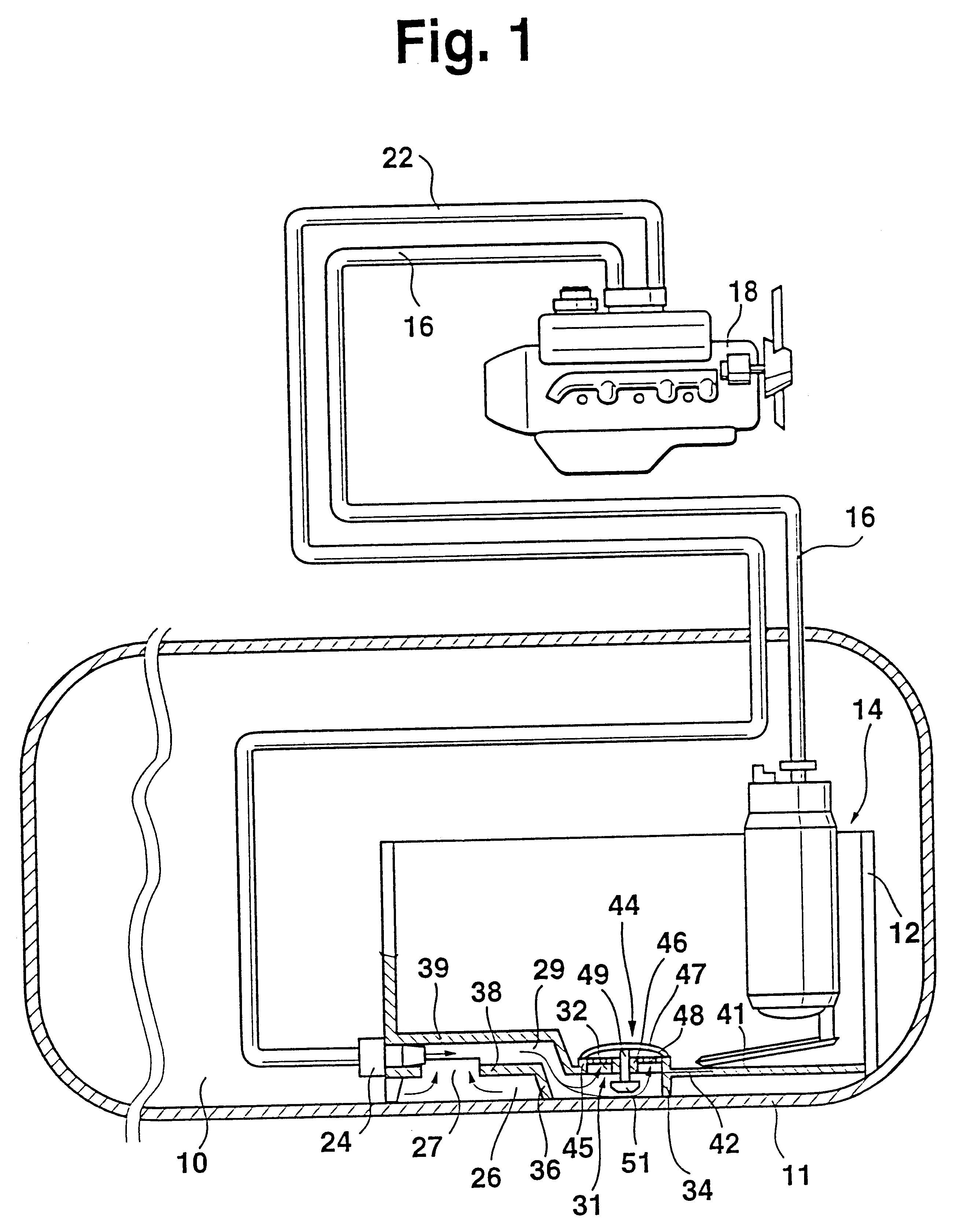
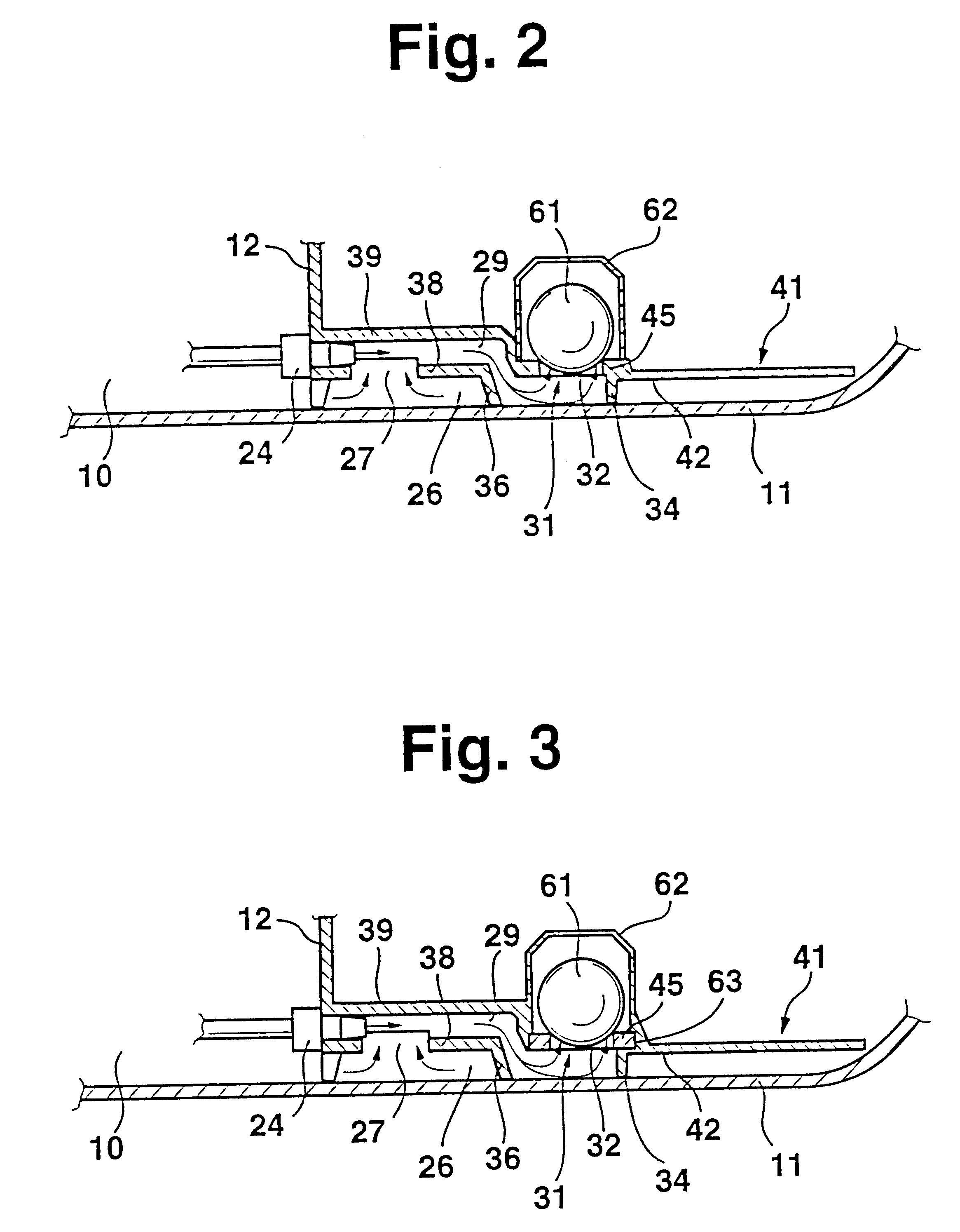
In the lower region of the reserve pot 12, near a tank bottom 11, a tank chamber 26 is provided which is open to the fuel tank 10. Via an o...


PUM


Abstract

The device for conveying fuel from a fuel tank (10) to an engine (18) of a motor vehicle has a conveying unit (14), communicating on the intake side with the fuel tank (10) and, on the pressurized side, with the engine (18), and a return line (22), which leads to a jet pump (24), located near a tank bottom (11), that pumps excess fuel via a mixing region into a reserve pot (12), from which the conveying unit (14) draws fuel. According to the invention a siphon-like mixing region (29) is provided between the reserve pot (12) and the tank bottom (11). An opening (32) or a filter element (48) is provided in a transitional region (31) of the mixing region (29) to the reserve pot (12). The opening (32) or filter element (48) which extends parallel to the tank bottom is closable by an axially movable closing element (44,51) so that a fuel flow can occur into the reserve pot (12) but not back from the reserve pot (12) into the mixing region (29).

Description

1. Field of the InventionThe invention relates to a device for conveying fuel from a fuel tank to the internal combustion engine of a motor vehicle having a conveying unit communicating on the intake side with the fuel tank and on the pressurized side with the engine, and a return line which leads to a jet pump, located near a tank bottom, that pumps the excess fuel via a mixing region into a reserve pot, from which the conveying unit draws fuel.2. Prior ArtIn conveying devices in accordance with German Patent Disclosure DE 42 24 981 A1, with the aid of the jet pump an adequate filling of a reserve pot is to be assured, in which reserve pot the conveying unit is disposed and from which the fuel is fed to the engine. This is intended to assure a fuel reserve for the conveying unit even if the fuel tank is relatively empty, and this reserve assures that even relatively long hill uphill grades, for instance, can be overcome without problems. To fill the reserve pot, in the lower region...

Claims


Application Information

Patent Timeline
IPC IPC(8): B01D35/027B01D35/00F02M37/08F02M37/18F02M37/10B60K15/03F02M37/22
CPCB01D35/0273F02M37/18F02M37/106F02M2037/228F02M37/50Y10T137/86075Y10T137/86212Y10T137/86228F02M37/10
Inventor KLEPPNER, STEPHAN
Owner ROBERT BOSCH GMBH
Why Eureka
Try Eureka