
Folding two wheeled vehicle

a two-wheeled vehicle and folding technology, applied in the field of bicycles and scooters, can solve the problems of many designs being somewhat unstable, difficult to open out for use, and inconvenient to carry,

Inactive Publication Date: 2001-08-14
SKOOT INT
View PDF8 Cites 73 Cited by
  • Summary
  • Abstract
  • Description
  • Claims
  • Application Information

AI Technical Summary

Benefits of technology

A principal aim of the present invention is to mitigate the disadvantages of the various known designs of folding bicycles, as described above, and so to provide a two wheeled vehicle which may be constructed to be light, safe in use and yet fold into an integral casing of a size which allows easy carrying or storage when not in use.
With the arrangement of this invention, there is a fixed relationship between the head section in which is journalled the front wheel carrier, the saddle pillar mount and the bottom bracket, which normally supports the pedal shaft. The relationship between these components remains constant, when the bicycle is both in its folded position and in its active (unfolded) position. In this way, the main frame of the bicycle may have the dimensions and geometry of a conventional "double-diamond frame" adult bicycle, whilst still being collapsible to a size which is readily portable.
The handles of the handlebar assembly, a steering column forming a part of the handlebar assembly and also the carrier for the front wheel all may incorporate a similar design of locking joint which permits the parts at the joint to pivot with respect to each other, and also to be locked in an active position. Such a joint may have two parts pivoted together about a transverse axis and a sleeve which may be moved closely to surround the pivot region when the parts are aligned co-axially, the sleeve then preventing relative pivotal movement between the parts. One of the parts may have an external screw thread engageable with corresponding internal screw threads at one end of the sleeve, to secure the sleeve in its locking position. A quick-release bayonet-type of threaded connector may be employed. In addition, the sleeve may have a conical internal surface which engages a corresponding conical surface on the other part when the sleeve locks the two parts together, so as to resist relative motion between the parts.
The rear wheel may have a mudguard which is secured to the rear wheel sub-frame for movement therewith. Such a mudguard may incorporate a shield to envelop the chain and sprockets, to protect a user from contacting the chain and sprockets, both when the bicycle is folded and when in its active state.

Problems solved by technology

However, the shape and dimensions of these when folded often are most inconvenient for carrying.
There have also been proposals where the main frame is designed to hinge to a collapsed position, with protruding parts hinging or telescoping with respect to the main frame, but these tend to be difficult to open out for use, or to collapse for carrying.
Moreover, many designs are somewhat unstable when unfolded and so unsettling to ride.
In an attempt to make a folding bicycle more easy to carry when folded, it is also known to provide a separate rigid case or flexible bag in which the collapsed bicycle is placed, but there then results the problem of transporting the case or bag, when the bicycle is in use.
A disadvantage of this arrangement is that the main chain wheel (driven by the pedals) must be of a relatively small diameter to fit within the case and not protrude when the bicycle has been folded.
To overcome this problem and obtain suitable gearing, a second large diameter chain drive wheel is provided on the pivoting arm section, so greatly adding to the mechanical complexity and weight of the structure, as a whole.
The disadvantage of this arrangement is that the length of the case will determine the distance between the front and rear wheels when the bicycle is unfolded as the location of the rear wheel axle is fixed within the case and the front wheel axle cannot lie significantly beyond the vertical front edge of the case.
Since a bicycle must have a certain minimum dimension between the front and rear wheel axles for safety in use, a relatively long and consequently heavy case is required.
Such an assembly, having many pivoted parts, does not provide a rigid structure defining the required geometery for a bicycle and of necessity it has a very low gearing.

Method used


Image

  • Folding two wheeled vehicle
  • Folding two wheeled vehicle
  • Folding two wheeled vehicle

Examples


Embodiment Construction

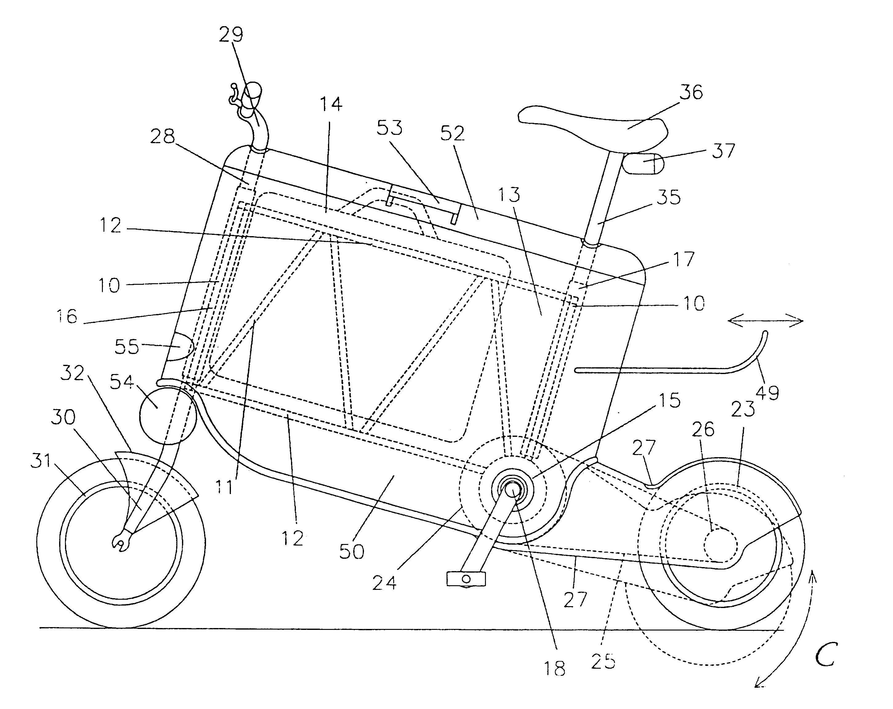
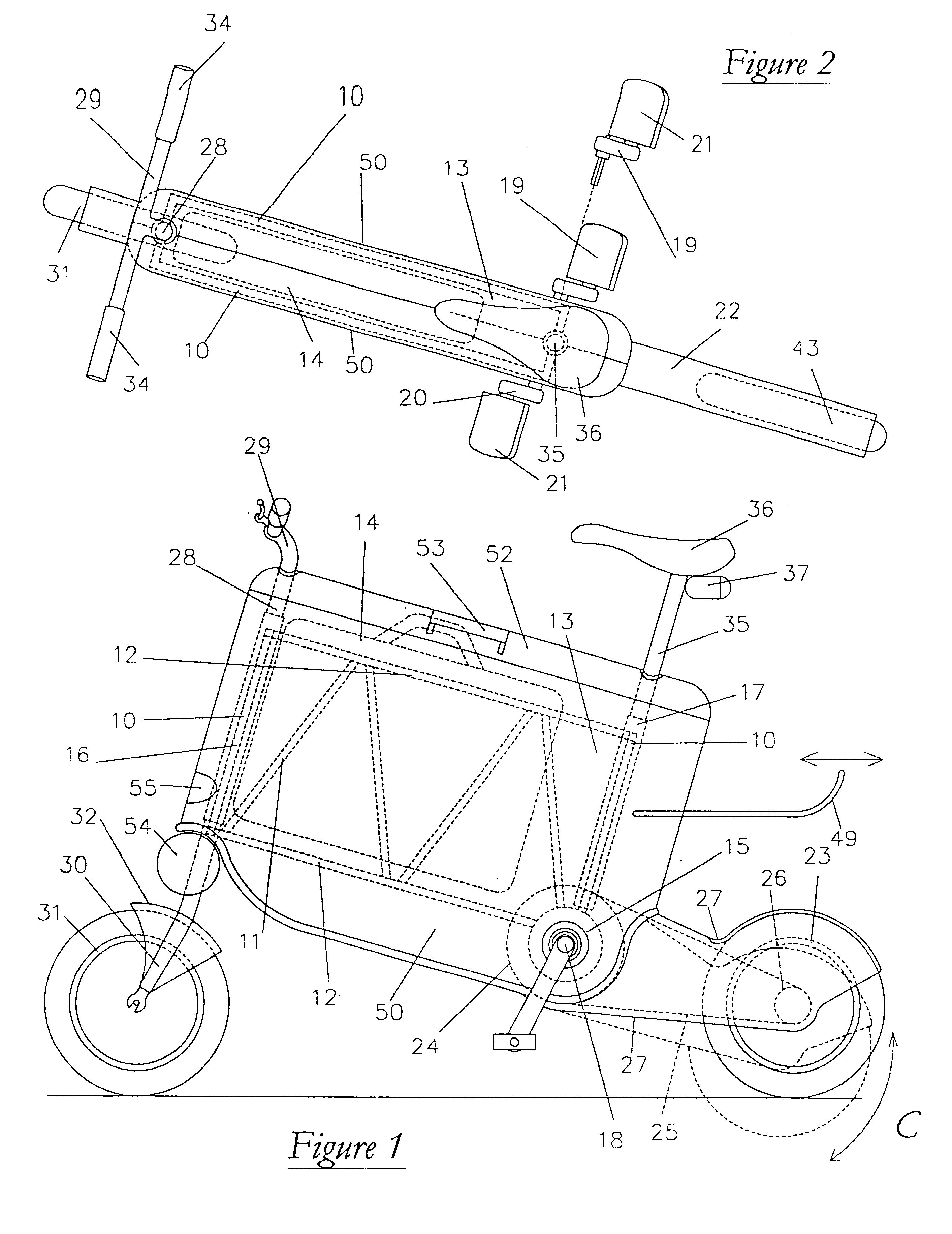
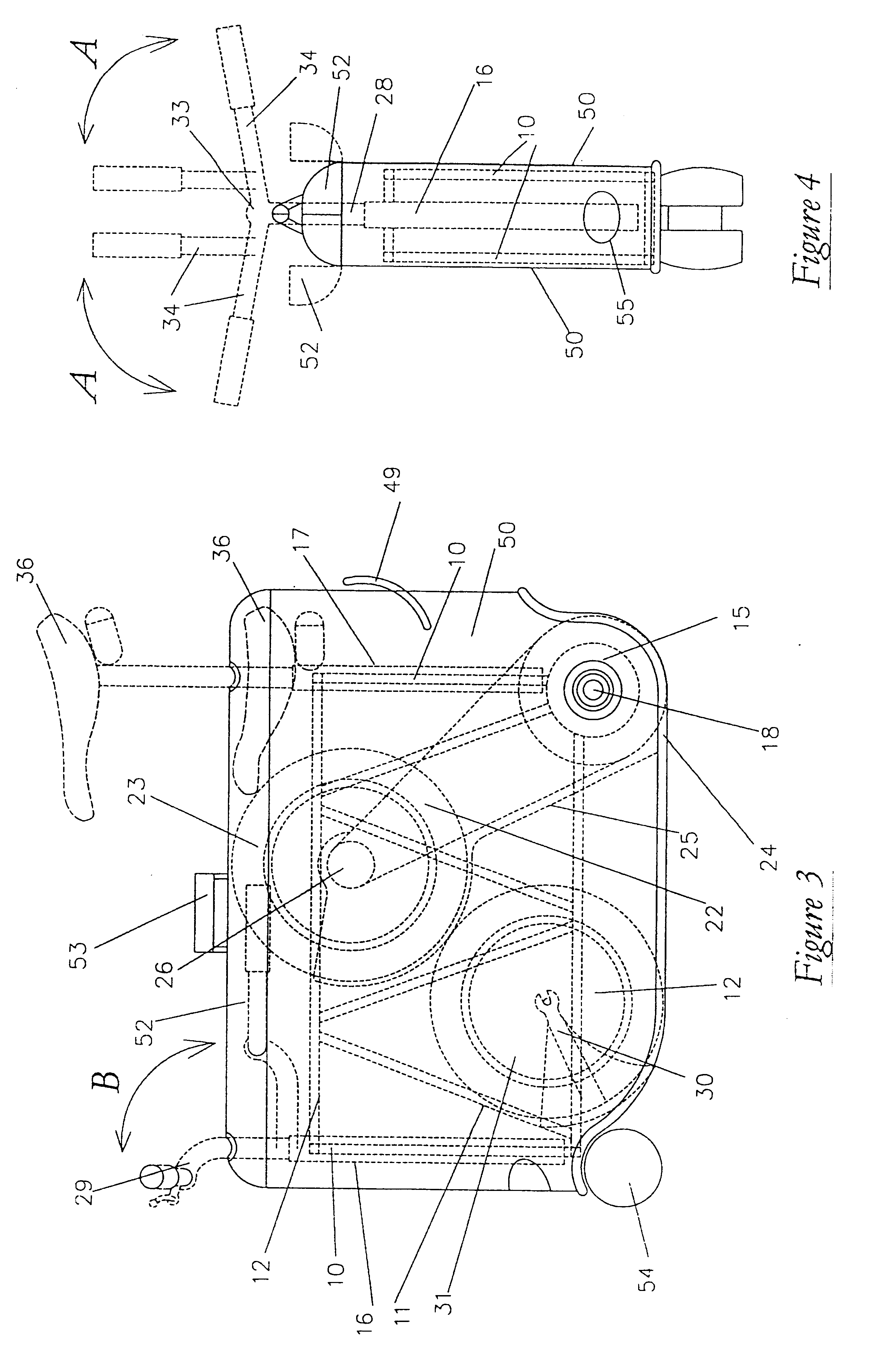
Referring initially to FIGS. 1 to 7, there is shown a first embodiment of bicycle of this invention. This comprises a main frame 10 constructed from metal (such as aluminium or titanium) members 11 welded together to form a kind of space frame, of a generally rectangular shape when viewed from the side. The frame 10 includes cross members 12, but there is a void 13 between the frame side members, able to accommodate a typical brief case or other luggage, shown in broken lines in FIG. 1 at 14. The frame could be made of other materials besides metal.

The main frame includes a bottom bracket 15, a head section 16 and a saddle pillar mount 17, all in a fixed relative disposition. The bottom bracket 15 rotatably supports a pedal shaft 18 (to be described in more detail below) which carries a pair of opposed cranks 19, 20, each crank rotatably supporting a respective pedal 21. Also journalled about the bottom bracket 15 is a rear wheel sub-frame 22 carrying at its outer end a rear wheel 2...


PUM


Abstract

A collapsible two wheeled vehicle comprises a substantially rigid main structural frame (10) defining a head section (16), a saddle pillar mount (17) and a bottom bracket (15). A rear wheel sub-frame (22) is pivoted to the frame (10) about the bottom bracket (15), and carriers a rear wheel (23), the sub-frame (22) being arranged for movement between a folded position where the rear wheel lies within the frame, between the head section (16) and the saddle pillar mount (17), and an active position where the sub-frame projects rearwardly beyond the frame. A pedal arrangement (19, 20, 21) is journalled in the bottom bracket (15) and drives the rear wheel (23) through an endless chain (25). A front wheel carrier is journalled to the head section (16) of the frame and has an arm (30) rotatably supporting a front wheel (31), the arm (30) being pivoted to the carrier for movement between a folded position where the front wheel (31) lies adjacent the rear wheel (23) when the sub-frame is in its folded position, and an active position where the arm projects generally downwardly from the carrier. The frame (1) carriers two opposed side panels (50) which are dimensioned so that the folded rear wheel sub-frame, rear wheel, front wheel carrier, folded arm and front wheel all lie substantially wholly within the confines of the side panels, the rear and front wheels lying outside the confines of the side panels when the sub-frame and arm are in their respective active positions.

Description

The present invention relates to a folding two wheeled vehicle such as a bicycle, a scooter or a lightweight pedal-assisted motorised bicycle, which may be folded so as to be easily portable when not in use as a vehicle.BACKGROUND OF THE INVENTIONThere are various designs of bicycles and scooters (hereinafter referred to simply as a bicycle) which may be folded for storage or carrying purposes. Some of these have a conventional bicycle frame of a diamond configuration and standard diameter wheels carried on arms hinged to the main frame, or removable wheels to permit folding of the frame. However, the shape and dimensions of these when folded often are most inconvenient for carrying. There have also been proposals where the main frame is designed to hinge to a collapsed position, with protruding parts hinging or telescoping with respect to the main frame, but these tend to be difficult to open out for use, or to collapse for carrying. Moreover, many designs are somewhat unstable whe...

Claims


Application Information

Patent Timeline
Patent Type & Authority Patents(United States)
IPC IPC(8): B62K15/00
CPCB62K15/008Y10T74/20792B62K2204/00B62K2015/005
Inventor FALLON, VINCENTMOORE, RICHARD JOHN ALBERT
Owner SKOOT INT
Learn More