Cemented carbide cutting insert having integral structure for securing the insert in a holder

a technology of integral structure and cutting insert, which is applied in the direction of tool workpiece connection, shaping cutter, manufacturing tools, etc., can solve the problems of less strength and difficult manipulation of tools, and achieve the effect of improving strength, easy manipulation, and easy mounting of such cutting inserts

Inactive Publication Date: 2001-08-14
SECO TOOLS AB
View PDF12 Cites 41 Cited by
  • Summary
  • Abstract
  • Description
  • Claims
  • Application Information

AI Technical Summary

Benefits of technology

Another object of the present invention is to provide a tool for cutting machining and a cutting insert with improved strength and which is easy to manipulate.
Still another object of the present invention is to provide a tool for cutt

Problems solved by technology

The problem of prior art tools of the above-noted types is that if these tools are of sm

Method used


Image

  • Cemented carbide cutting insert having integral structure for securing the insert in a holder
  • Cemented carbide cutting insert having integral structure for securing the insert in a holder
  • Cemented carbide cutting insert having integral structure for securing the insert in a holder

Examples


Embodiment Construction

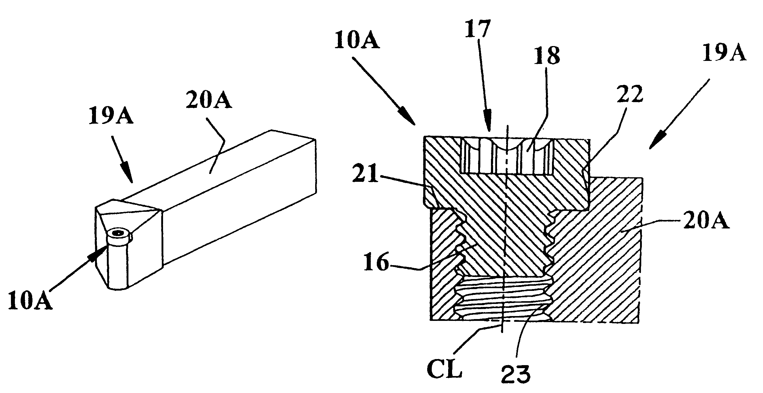
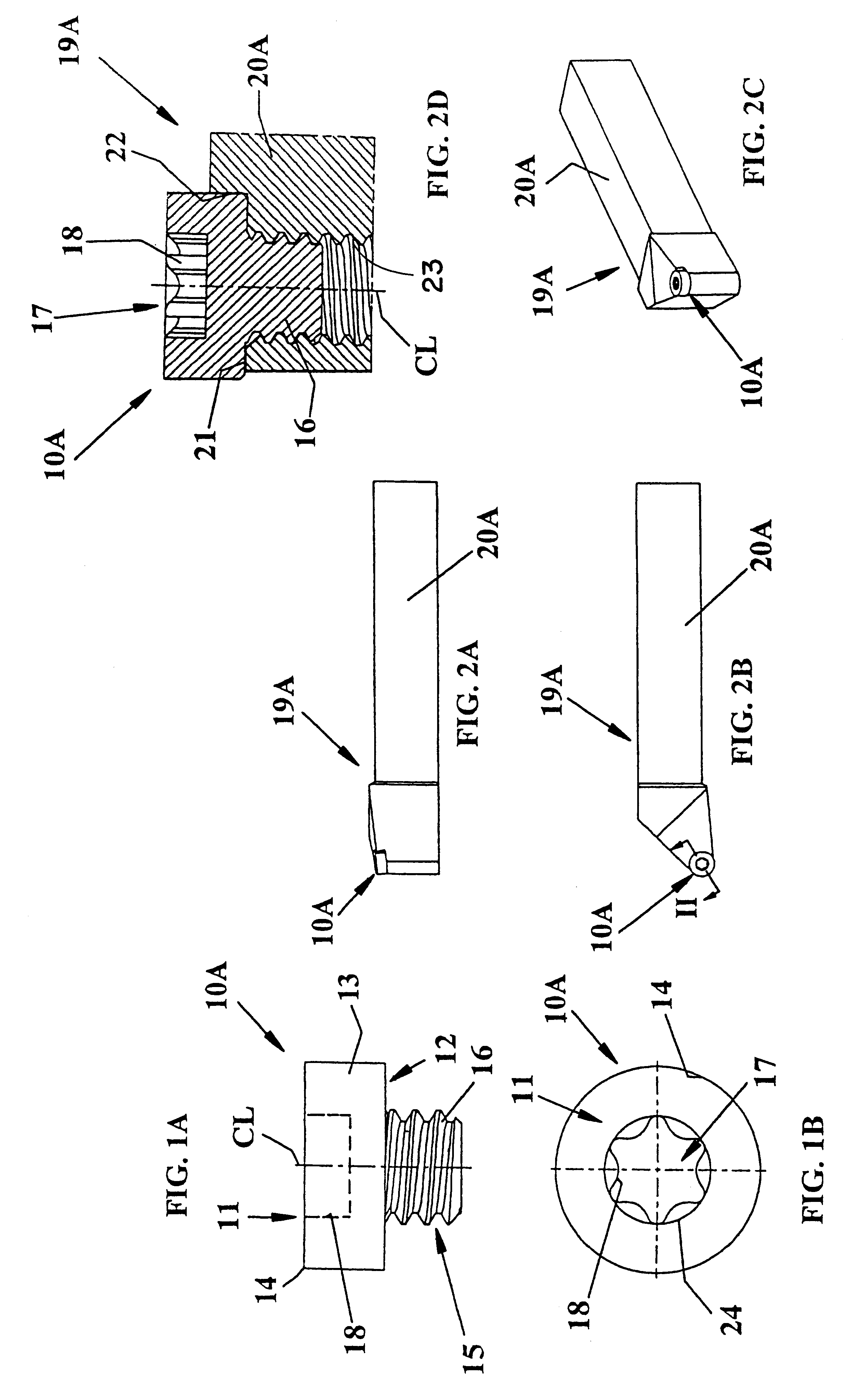
In FIGS. 1A and 1B is shown a cutting insert 10A according to the present invention, which insert preferably is intended for longitudinal turning.

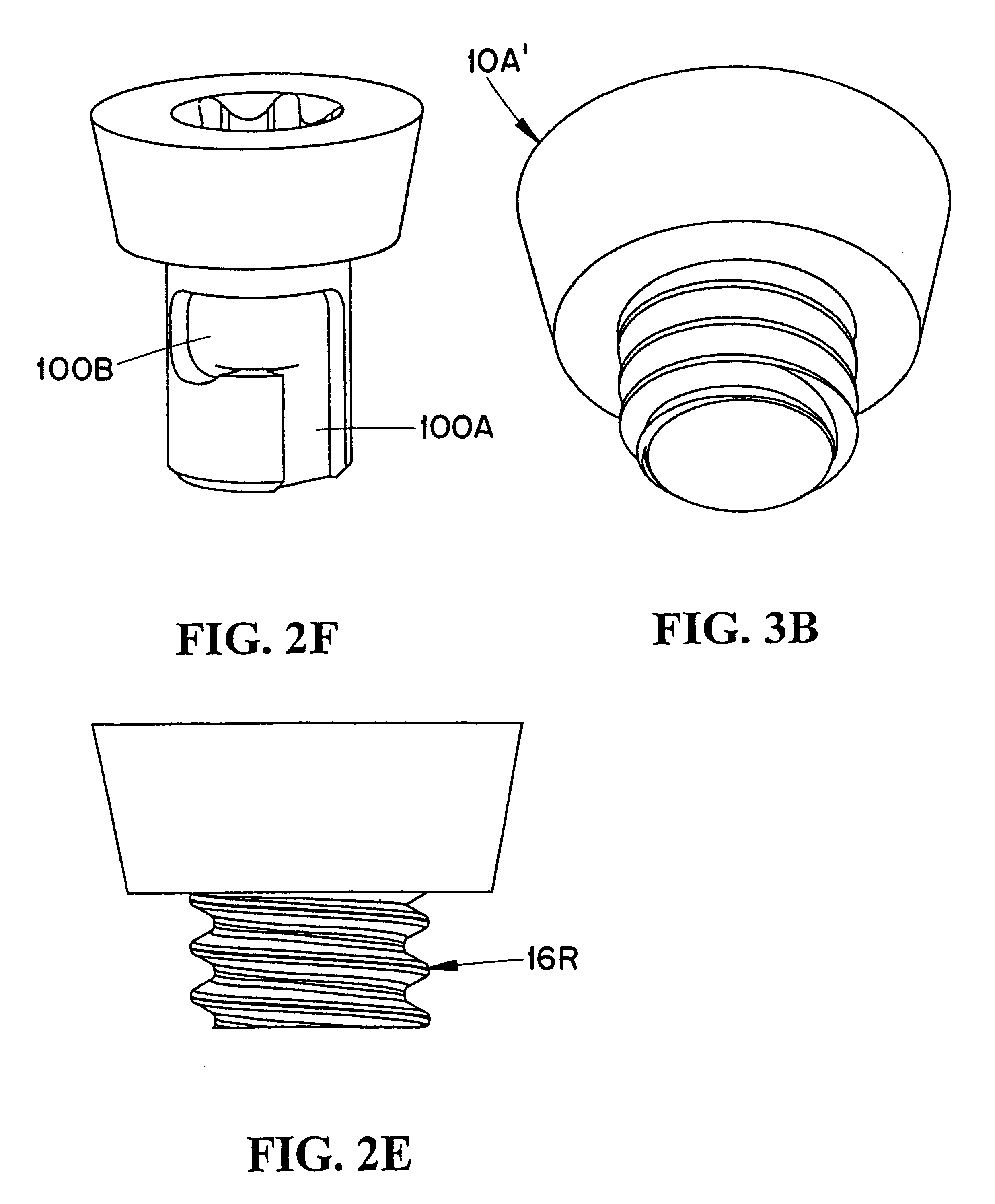
The cutting insert 10A has a round geometry of so called R type. The cutting insert has an upper side 11 and a substantially planar, opposite lower side 12, the sides 11, 12 being interconnected by a cylindrical edge surface 13. The cutting insert has a circular cutting edge 14 formed along a line of intersection between the upper side 11 and the edge surface 13. The cutting insert 10A has a center line CL. The cutting insert comprises securing means 15 to be used for securing the cutting insert against a holder. The diameter of the cutting insert is considerably larger than the diameter of the securing means 15. The securing means 15 is integrated with the cutting insert and thereby formed of the same material as the cutting edge 14. This has been obtained through injection molding with suitable equipment and subsequent sintering. The cut...


PUM

PropertyMeasurementUnit
Forceaaaaaaaaaa

Abstract

A cutting insert intended for chip removing machining includes a body forming at least one cutting edge, a securing structure such as a helical thread disposed at one side of the body, and a key grip such as a profiled recess disposed at an opposite side. The insert is formed of injection molded cemented carbide such that the body, the securing structure, and the key grip are all integral with one another. The insert is secured in a holder by rotating the insert using a key which engages the key grip, whereupon the securing structure engages a complementary securing structure on the holder to pull the insert body against the holder.

Description

The present invention relates to a tool for cutting machining, a cutting insert and a method for mounting such a cutting insert.PRIOR ARTTraditionally circular indexable inserts are used having a diameter down to about 5 mm. The smallest circular indexable inserts are to be regarded as rings of cemented carbide in order to obtain space enough to accommodate a retaining screw, which holds the cutting insert in the cutting insert pocket. Through WO 98 / 13161 is previously known a ball nose milling cutter comprising a milling head attached via a pull rod to a shank. The milling head comprises injection molded cemented carbide and has a cutting edge which extends towards the rotational axis of the tool. The milling head has a thread, which is integral with, and thereby made of the same material as, the cutting edge. The milling head comprises a key grip consisting of diametrical opposite planar surfaces. Through WO 95 / 33590 is previously known an injection molded cutting insert with an i...

Claims


Application Information

Patent Timeline
IPC IPC(8): B23B27/16B23B27/00B23B51/04B23C5/16B23C5/10B23C5/22B23B27/08
CPCB23B27/007B23B27/16B23B51/048B23C5/10B23C5/22B23B2226/125B23B2226/31B23B2240/04Y10T407/20B23B2265/34B23C2210/03Y10T407/27Y10T407/2272B23B2260/138B23B51/00
Inventor JORDBERG, JONAS
Owner SECO TOOLS AB
Why Eureka
Try Eureka