Permanent magnetically excited electrical rotary drive

a permanent magnetically excited, electrical rotary drive technology, applied in the direction of motor/generator/converter stopper, dynamo-electric converter control, prosthesis, etc., can solve the problems of severe, possible even fatal, and inability to ensure the correct functioning of the driv

Inactive Publication Date: 2001-08-21
THORATEC CORPORTION
View PDF24 Cites 131 Cited by
  • Summary
  • Abstract
  • Description
  • Claims
  • Application Information

AI Technical Summary

Problems solved by technology

A problem in known rotary drives for blood pumps is that when faults arise, such as, for example, the failure of an amplifier circuit or the breakage of an electrical line in one of the phases of the dr

Method used


Image

  • Permanent magnetically excited electrical rotary drive
  • Permanent magnetically excited electrical rotary drive
  • Permanent magnetically excited electrical rotary drive

Examples


Embodiment Construction

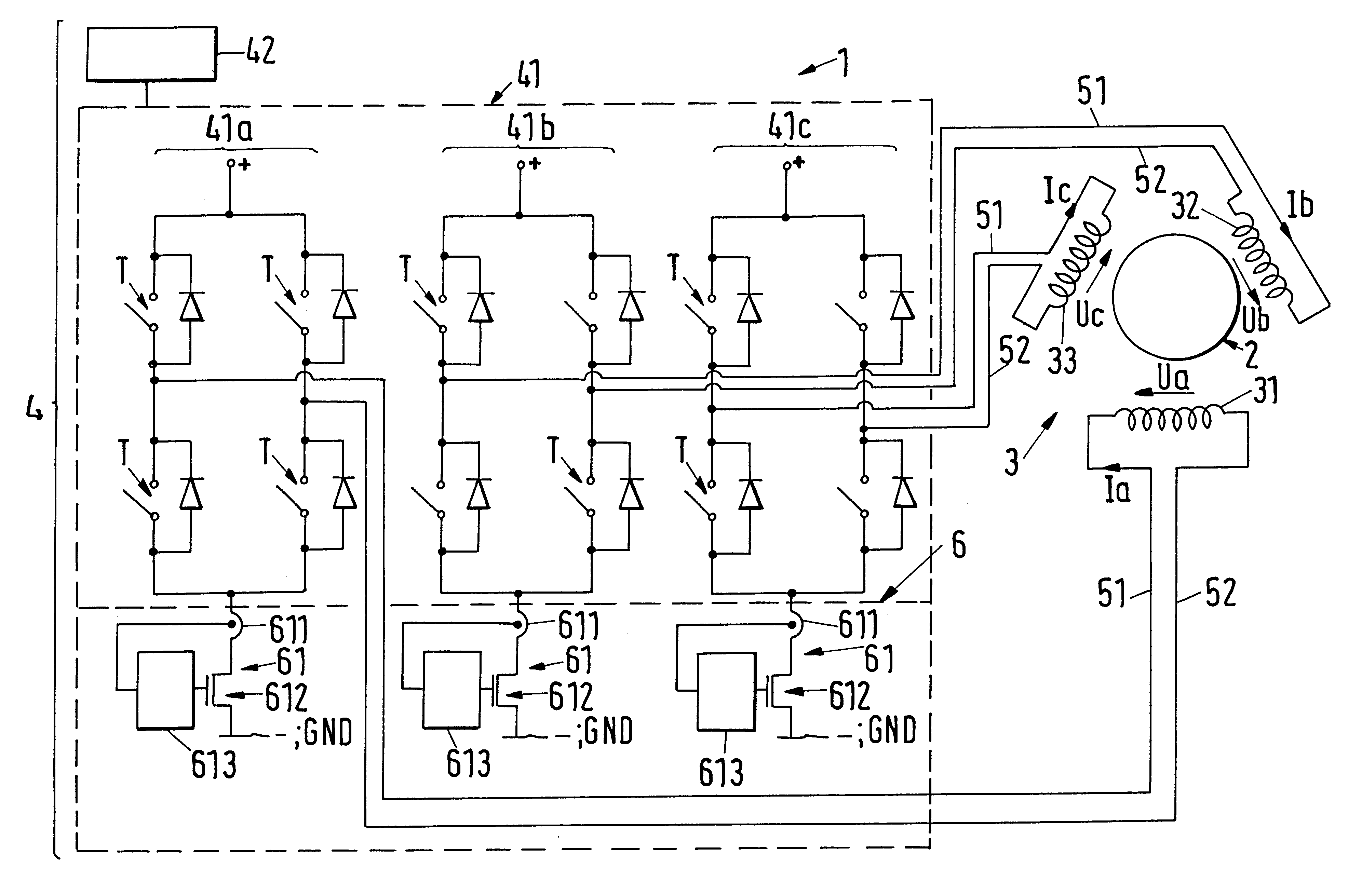
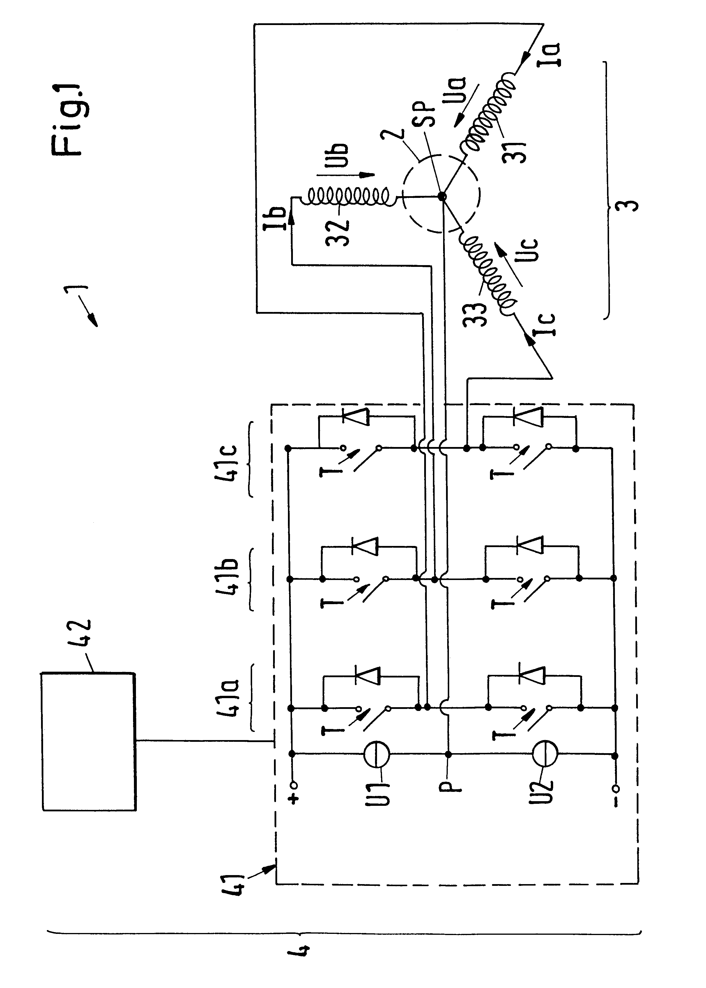
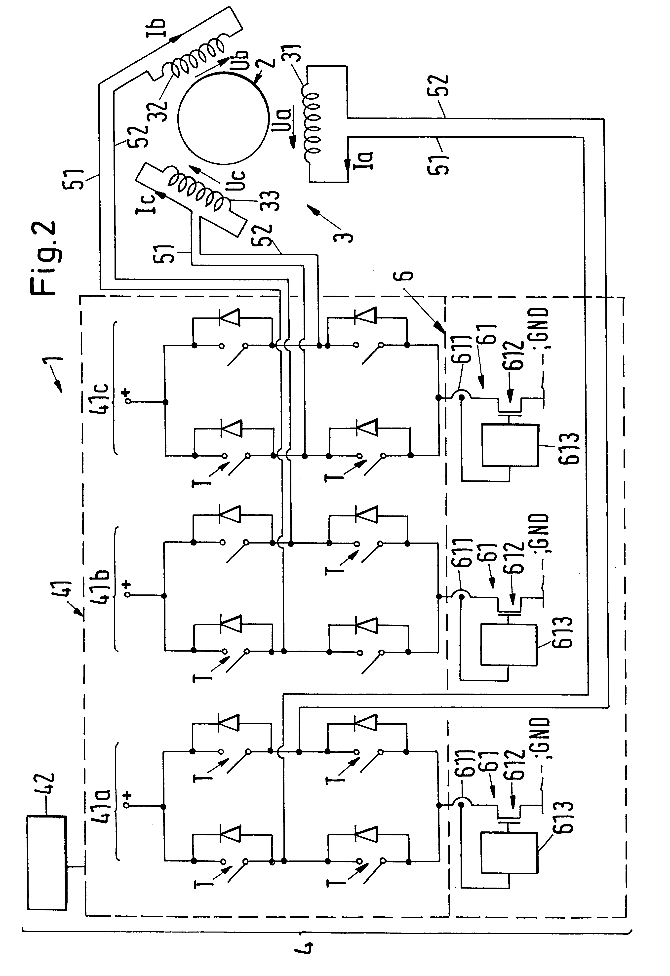
FIG. 1 shows, in a schematic illustration, a first exemplary embodiment of the permanent magnetically excited electrical rotary drive in accordance with the invention, which is designated in its entirety by the reference symbol 1. The rotary drive 1 comprises a permanent magnetic rotor 2, a stator 3 and a setting device 4 with an amplifier element 41 and a regulation unit 42.

The stator 3 has a drive winding which has three loops 31, 32, 33 in this exemplary embodiment, each of which belongs to a different electrical phase, which means that the drive winding is designed to be three phased. By means of the drive winding a magnetic rotary field can be produced as a drive field which produces a torque on the rotor 2, through which the latter is set into rotation.

In the following, reference is made to the case, which is particularly important in practice, that the drive winding is designed to be three phased with three loops 31, 32, 33. It is, however, clear that the rotary drive in acco...


PUM


Abstract

A permanent magnetically excited electrical rotary drive for a blood pump is proposed, comprising a permanent magnetic rotor and a stator, said stator comprising a drive winding having at least two loops for the production of a magnetic drive field which produces a torque on the rotor, with each loop belonging to a different electrical phase, furthermore comprising a setting device which supplies each loop in each case with a phase current or in each case with a phase voltage as a setting parameter, with the setting device comprising a separate power amplifier for each loop so that the setting parameter for each loop can be regulated independently of the setting parameter for the other loops.

Description

1. Field of the InventionThe invention relates to a permanent magnetically excited electrical rotary drive for a blood pump and to a blood pump with a rotary drive of this kind.2. Description of the Prior ArtBlood pumps, which are usually designed as axial or as centrifugal pumps, serve for the forwarding of blood and are used, for example, in the framework of operations on the heart for maintaining the blood circulation. Furthermore, implantable blood pumps are known which are implanted into the body of the patient for the temporary or chronic support of the heart activity.In blood pumps it must be ensured that no contamination of the forwarded blood arises. Therefore, the rotor of the electromagnetic drive and / or the pump rotor is preferably magnetically journalled in blood pumps. This magnetic journalling of the rotor can be realized either through separate magnetic bearings, that is ones which are different from the drive; or the magnetic journalling is realized through the stat...

Claims


Application Information

Patent Timeline
IPC IPC(8): A61M1/10F16C39/06F16C39/00H02K7/09H02K29/06H02K29/08H02P6/00H02P6/08H02P6/20A61M60/178A61M60/232A61M60/422A61M60/822A61M60/824
CPCA61M1/101F16C32/0457F16C32/0493H02K7/09A61M1/1031H02P6/08H02P6/20A61M1/1015A61M1/1017H02K29/08F16C2316/18A61M2205/3334A61M60/824A61M60/422A61M60/232A61M60/178A61M60/822
Inventor SCHOB, RETO
Owner THORATEC CORPORTION
Why Eureka
Try Eureka