Microchannel apparatus and method of producing emulsions making use thereof

Inactive Publication Date: 2001-08-28
NORINSUISANSHO SHOKUHIN SOGO KENKYUSHOCHO +1
View PDF11 Cites 173 Cited by
  • Summary
  • Abstract
  • Description
  • Claims
  • Application Information

AI Technical Summary

Problems solved by technology

The general methods mentioned above have a disadvantage in that diameters of dispersed phase particles in a continuous phase are distributed over a wide range.
The method using filtration through a membrane comprising polycarbonate and the method using repeated filtrations through a PTFE membrane theoretically cannot manufacture emulsions comprising particles larger than the membrane pores and cannot separate particles smaller than the membrane pores.
These methods are, therefore, especially unsuitable for producing emulsions comprising large particles.
In addition, these met

Method used


Image

  • Microchannel apparatus and method of producing emulsions making use thereof

Examples


Embodiment Construction

Preferred embodiments of the present invention will now be described referring to the attached figures.

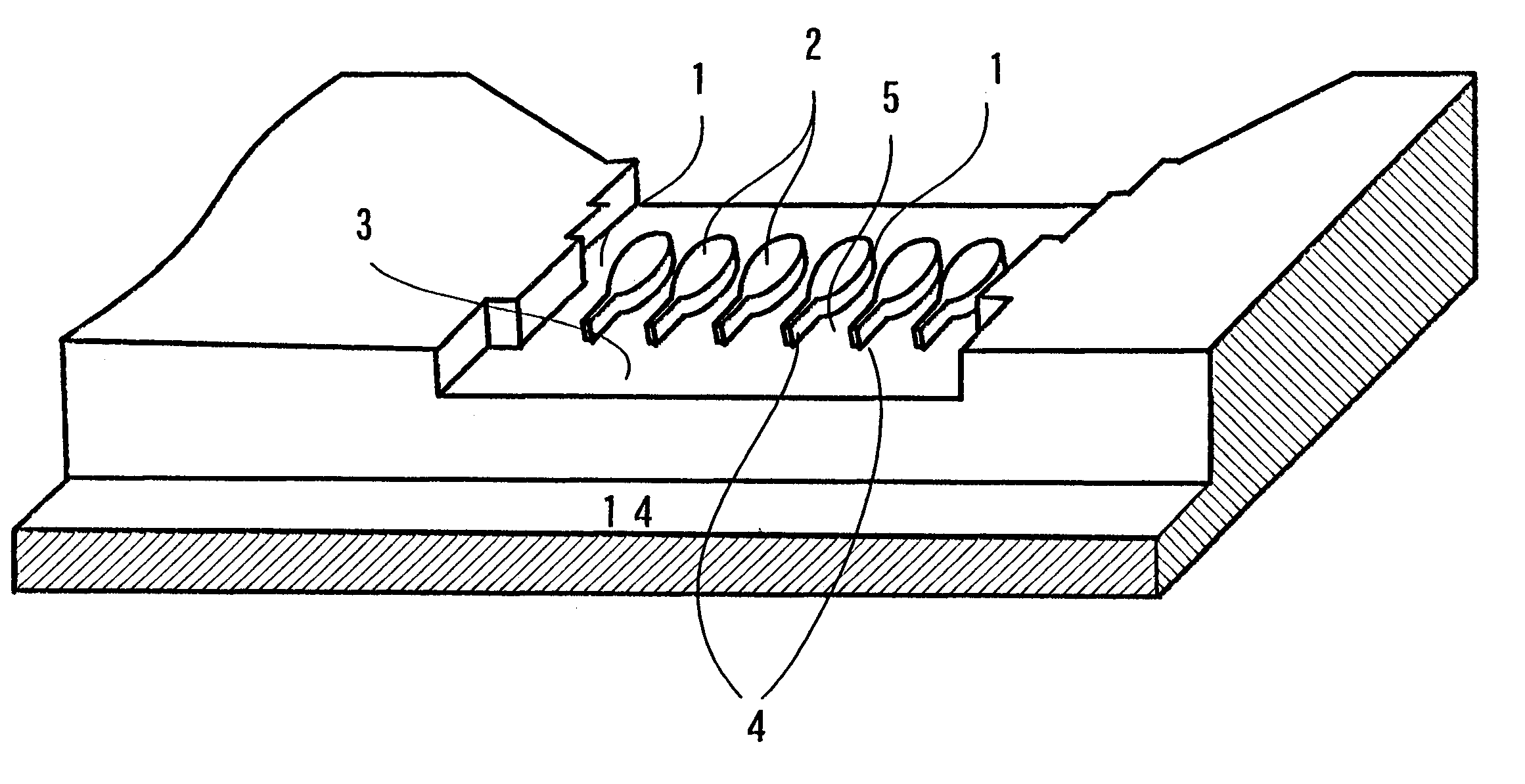
In the microchannel apparatus according to the present invention, a microchannel 1 is formed between adjacent convex portions 2 defined on a surface of a base 13, which convex portions 2 are formed on a terrace 3 which is also defined by the surface of the base as a boundary section between a continuous phase and a dispersed phase.

A partition wall 4 is formed extending from both ends of each convex portion 2 toward the continuous phase and the dispersed phase, respectively. The partition walls 4 are parallel each other and a flow path 5 is formed between the partition walls 4. The length of the partition wall 4 as shown in the figures does not reach to the ends of the terrace 3, however, the length of the partition wall 4 is not be limited to the depicted structure and may reach to the ends of the terrace 3.

It is preferable to adopt a wet etching process with photolithography used ...


PUM

PropertyMeasurementUnit
Lengthaaaaaaaaaa
Flow rateaaaaaaaaaa
Widthaaaaaaaaaa

Abstract

A microchannel apparatus includes a plural partition walls 4 formed as extensions of plural microchannels 1 toward a continuous phase, and a flow path 5 is formed between adjacent ones of the partition walls 4. A dispersed phase pumped into a continuous phase via each microchannel 1 generates nearly perfect spheres in the course of passing through the microchannel and the flow path 5 in between the partition walls 4, thereby producing emulsions comprising fine and homogenous microspheres.

Description

1. Field of the InventionThe present invention relates to a microchannel apparatus for producing emulsions used in the food industry, the manufacturing of drugs and cosmetics, etc., and to a method of producing emulsions making use thereof.2. Description of Related ArtTechniques in which a biphasic system, for which a separated state is thermodynamically stable, is formed, such as that composed of a water phase and an organic phase which are emulsified to obtain a semi-stable emulsion, are conventionally known. As general emulsification methods, there have been described in "Science of Emulsions" (Asakura-shoten, 1971), the methods of using a mixer, a colloid mill, a homogenizer, etc., and the method of dispersion with sound waves, which are all well-known.The general methods mentioned above have a disadvantage in that diameters of dispersed phase particles in a continuous phase are distributed over a wide range.Therefore, a method of using filtration by means of a membrane comprisi...

Claims


Application Information

Patent Timeline
IPC IPC(8): B01F13/00B01F3/08B01F5/06B01F25/46
CPCB01F3/0807B01F5/0475B01F13/0059Y10S516/924B01F2215/0031B01F2215/0032Y10S366/03B01F2215/0014Y10T137/87652Y10T137/0329B01F23/41B01F25/3142B01F33/30B01F2101/21B01F2101/06B01F2101/22
Inventor NAKAJIMA, MITSUTOSHINABETANI, HIROSHIKIKUCHI, YUJILARGUEZE, CHRISTOPHE
Owner NORINSUISANSHO SHOKUHIN SOGO KENKYUSHOCHO
Why Eureka
Try Eureka