Drive circuit for switching power supply

Inactive Publication Date: 2001-08-28
NAGANO JAPAN RADIO CO LTD
View PDF8 Cites 11 Cited by
  • Summary
  • Abstract
  • Description
  • Claims
  • Application Information

AI Technical Summary

Benefits of technology

The invention has been made to solve the above problems, and it is a main object of the invention to provide a drive circuit for a switching power supply, which is capable of preventing breakage of a main switching element and at the same time permits an increase in the range of switching control.
The drive circuit for a switching power supply includes a driving element for generating a drive signal for driving a main switching element, and a transformer for delivering the drive signal input via a capacitive element to a primary winding thereof, to the main switching element from a secondary winding thereof, the drive circuit being characterized by comprising an inductive element having an inductance value smaller than at least a value of an excitation inductance of the primary winding and allowing series resonance to be produced between the capacitive element and the inductive element.
This drive circuit increases the resonance frequency in the resonance phenomenon caused by the capacitive element and the inductive element upon stoppage of operation for generating power. Therefore, since the period of the series resonance frequency is shortened, a time period over which the resonance voltage waveform is above a threshold voltage of the switching element becomes shorter. For this reason, the switching element becomes difficult to turn on, and even when the switching element is turned on, the maximum value of a current flowing is reduced, whereby magnetic saturation of the switching transformer connected to the main switching element is prevented and hence breakage of the main switching element and the switching transformer is prevented. Further, by setting a capacitance value of the capacitive element to a suitable value, it is possible to minimize the amount of energy stored in the capacitive element. In this case, series reso

Problems solved by technology

As a result, magnetic saturation occurs in the transformer 24, which, for instance, causes

Method used


Image

  • Drive circuit for switching power supply
  • Drive circuit for switching power supply
  • Drive circuit for switching power supply

Examples


Example

(First Embodiment)

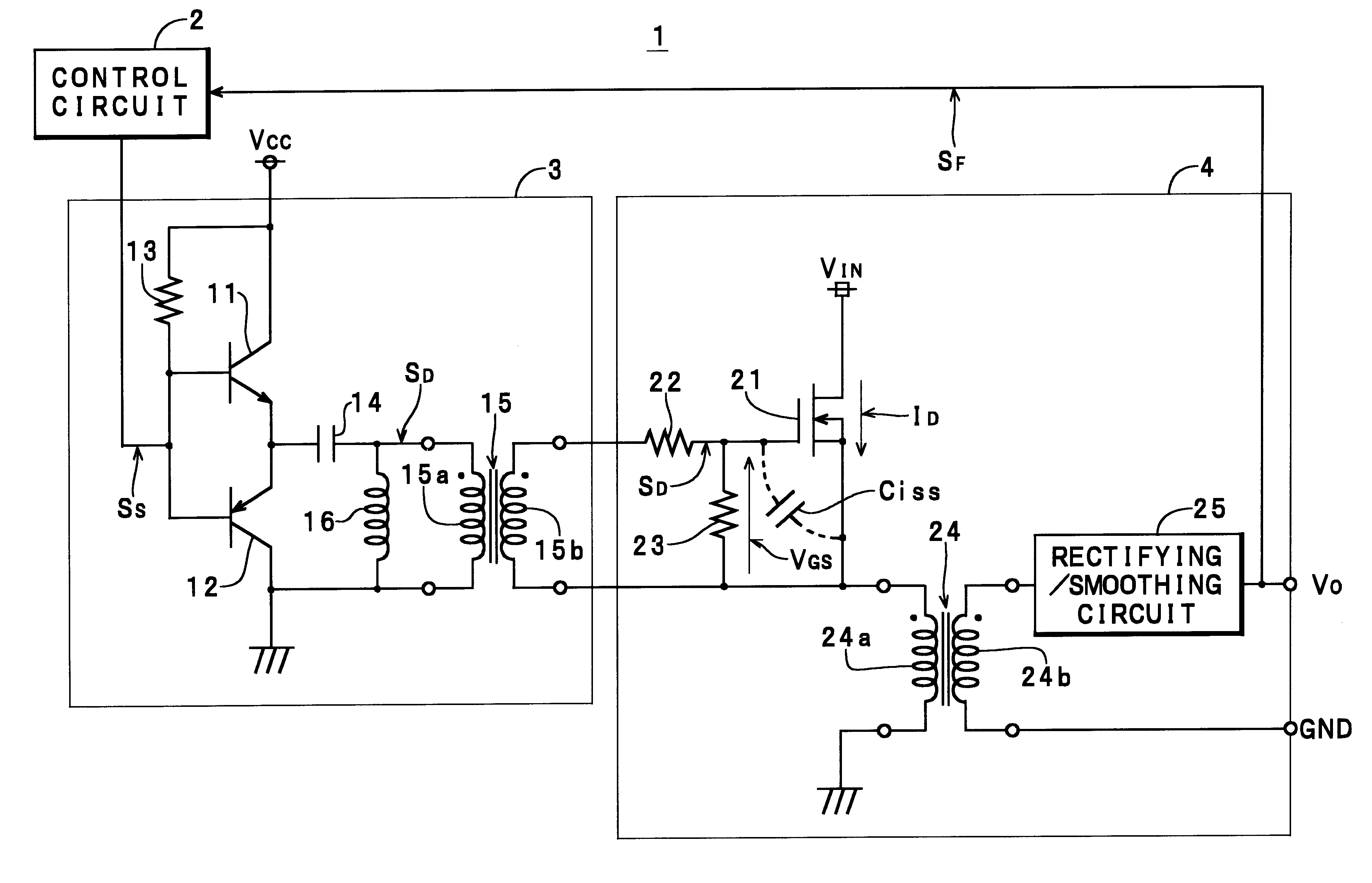
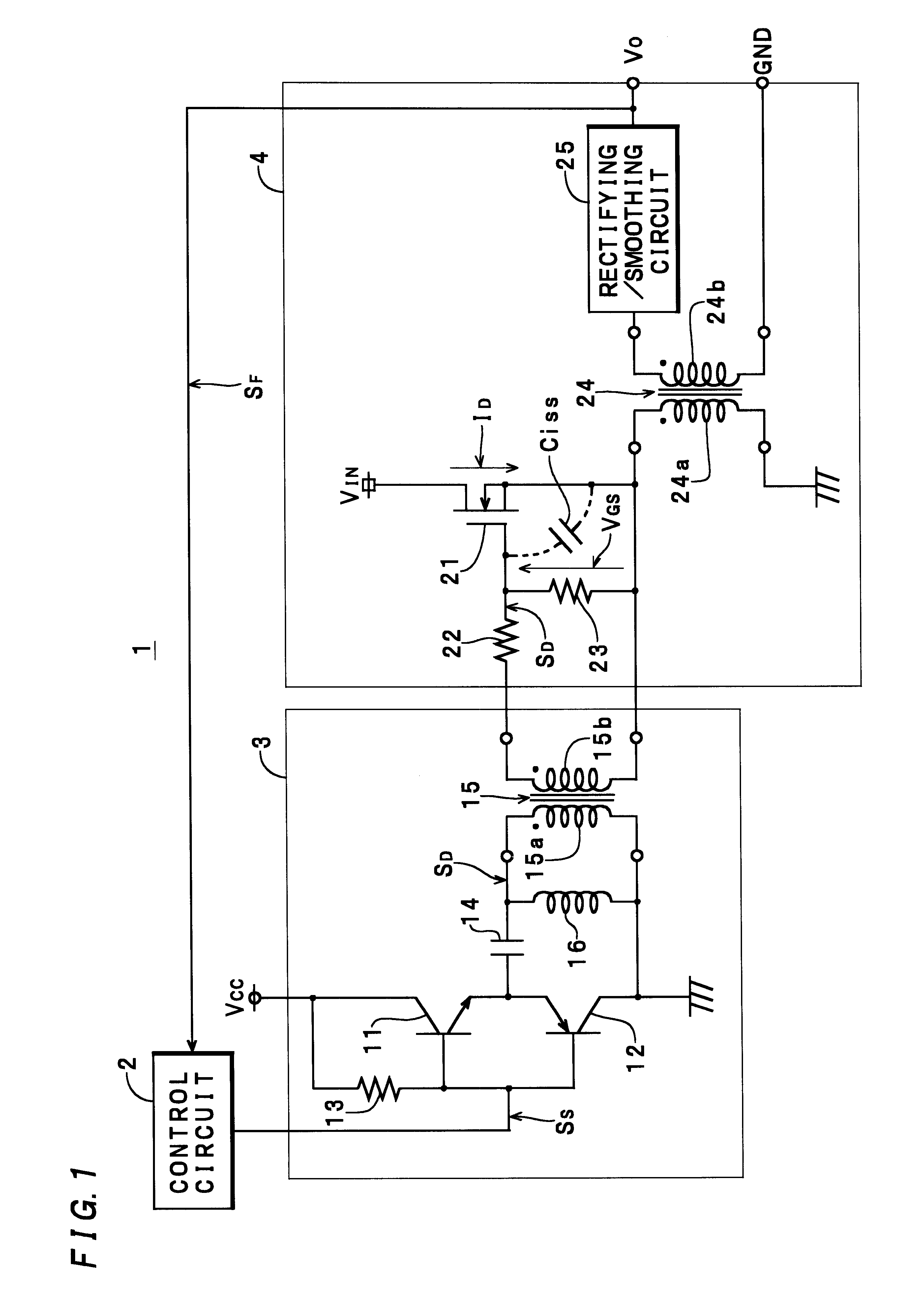
Referring first to FIG. 1, there is shown the circuitry of a power supply unit 1. The power supply unit 1 includes a control circuit 2 for generating a switching signal SS, a drive circuit 3, and a main circuit 4. The drive circuit 3 is comprised of a pair of an npn transistor 11 and a pnp transistor 12, which forms a complementary circuit, a pull-up resistor 13, a capacitor 14 corresponding to a capacitive element of the invention for blocking a DC current, a drive transformer 15 having a primary winding 15a and a secondary winding 15b at a turns ratio of 1:1, and an inductor 16 connected in parallel with the primary winding 15a and corresponding to an inductive element of the invention. The main circuit 4 is comprised of an n-channel MOS FET 21, which is a main switching element, bias resistors 22 and 23, a switching transformer 24, and a rectifying and smoothing circuit 25.

In the embodiment, a capacitance value C of the capacitor 14 and an inductance value L16 o...

Example

(Second Embodiment)

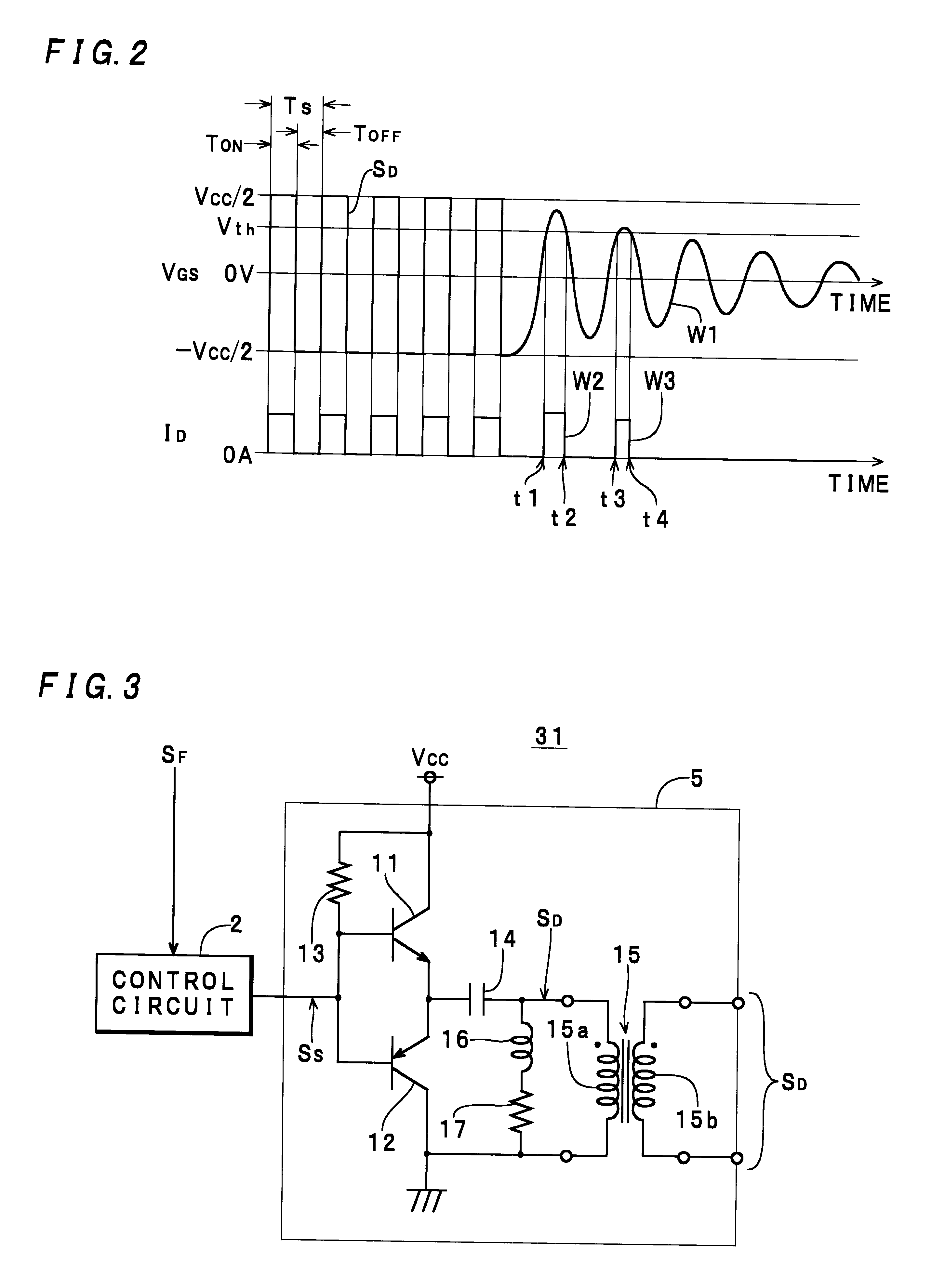
Next, description will be made of circuitry and operation of the power supply unit 31 which is formed by modifying part of the power supply unit 1, with reference to FIG. 3. Components corresponding to those of the first embodiment are indicated by identical reference numerals, and detailed description thereof will be omitted.

As shown in the figure, the power supply unit 31 is distinguished from the power supply unit 1 in that it has a drive circuit 5 in which a series circuit formed by an inductor 16 and a damper resistor 17 is connected in parallel with a primary winding 15a of the transformer 15.

When a control circuit 2 stops operating, a series resonance phenomenon occurs in a closed circuit formed by a capacitor 14, a parallel circuit formed by the series circuit of the inductor 16 and the resistor 17 and the primary winding 15a, and the emitter and collector of a transistor 12. In this case, energy stored in the capacitor 14 is lost at the resistor 17 during...


PUM


Abstract

A drive circuit for a switching power supply includes a driving element (11, 12) for generating a drive signal (SD), and a transformer (15) for outputting the drive signal input via a capacitive element to a primary winding (15a) thereof (14), to a main switching element (21) from a secondary winding (15b) thereof. The drive circuit (3) is constructed such that breakage of the main switching element (21) can be prevented while permitting an increase in the range of switching control. The drive circuit (3) is characterized by comprising an inductive element (16) having an inductance value smaller than at least a value of an excitation inductance of the primary winding (15a) and allowing series resonance to be produced between the capacitive element (14) and the inductive element (16).

Description

This invention relates to a drive circuit for a switching power supply, and more particularly to a drive circuit for a switching power supply, for delivering a drive signal to a main switching element via a drive transformer.Conventionally, a power supply unit 41 shown in FIG. 6 is well known as a switching power supply unit including a drive circuit of the above-mentioned kind. The power supply unit 41 is comprised of a control circuit 2 for generating a switching signal SS, a drive circuit 42 for carrying out power amplification of the switching signal SS, and a main circuit 4 for generating a DC voltage Vo by performing switching operation in synchronism with a drive signal SD delivered from the drive circuit 42.The drive circuit 42 is comprised of a pair of an npn transistor 11 and a pnp transistor 12 forming a complementary circuit, a pull-up resistor 13, a capacitor 14 for blocking DC current, and a drive transformer 15 having a primary winding 15a and a secondary winding 15b ...

Claims


Application Information

Patent Timeline
IPC IPC(8): H02M3/28H02M3/24H02M3/335H03K17/08H03K17/687
CPCH02M3/335H03K17/6877H03K17/691Y02B70/1433H03K2217/94042Y02B70/10
Inventor MINAMISAWA, TOSHITAKAMATSUZAKA, ATSUSHI
Owner NAGANO JAPAN RADIO CO LTD
Why Eureka
Try Eureka