
System for reconfiguring a boot device by swapping the logical device number of a user selected boot drive to a currently configured boot drive

Inactive Publication Date: 2001-08-28
KINGLITE HLDG INC
View PDF16 Cites 85 Cited by
  • Summary
  • Abstract
  • Description
  • Claims
  • Application Information

AI Technical Summary

Problems solved by technology

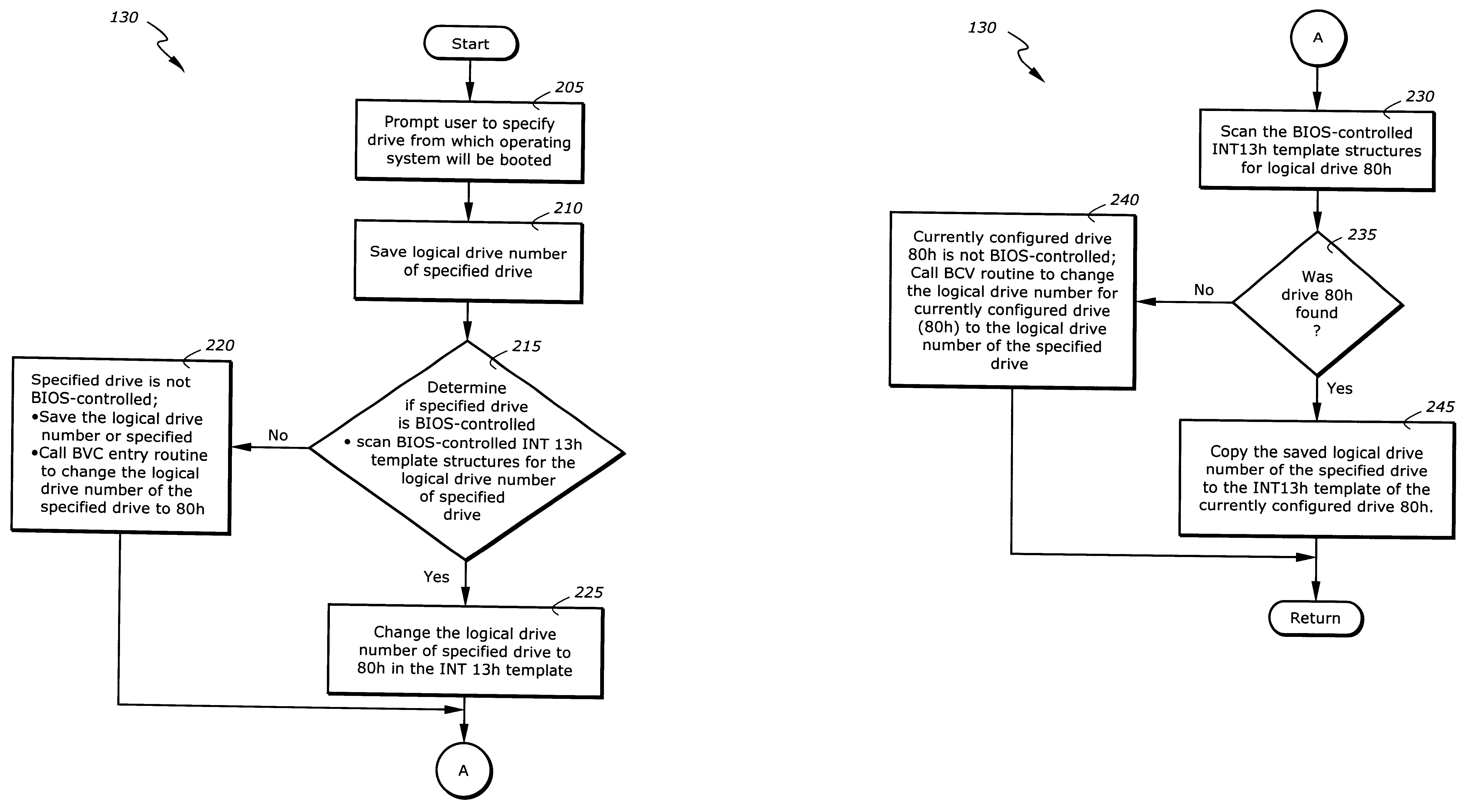
While this ensures that the boot process will commence from a specific drive, it poses a problem if the user determines, prior to booting, that the boot process should commence from another device.

Method used


Image

  • System for reconfiguring a boot device by swapping the logical device number of a user selected boot drive to a currently configured boot drive
  • System for reconfiguring a boot device by swapping the logical device number of a user selected boot drive to a currently configured boot drive
  • System for reconfiguring a boot device by swapping the logical device number of a user selected boot drive to a currently configured boot drive

Examples


Embodiment Construction

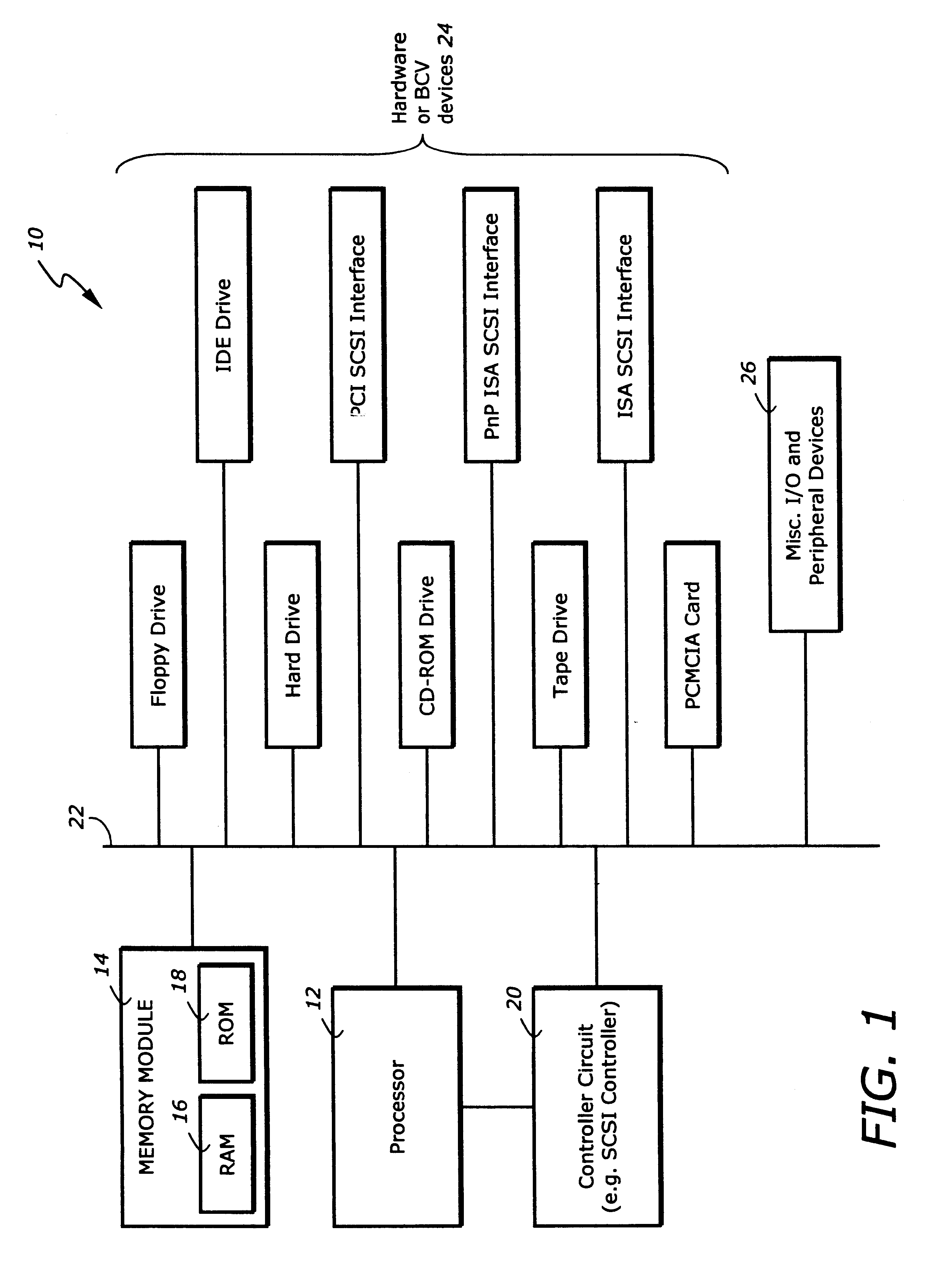
The present embodiment is described in reference to a processor system 10. FIG. 1 illustrates an exemplary processor system 10 which implements the processes of the present invention. The processor system 10 comprises a processor 12 and a memory module 14. The memory module 14 includes random access memory (RAM) 16 and read-only memory (ROM) 18. In one embodiment, the memory module 14 also includes a main memory or a dynamic random access memory (DRAM). The processing system 10 also comprises a controller circuit 20 such as a SCSI controller. The processor 12, memory module 14 and controller circuit 20 are coupled to a system bus 22. The processor system 10 also comprises hardware devices 24 and various I / O and peripheral devices 26 which are coupled to the system bus 22. Examples of the hardware devices 24 include, but are not limited to a floppy drive, a hard drive, a PCMCIA card, a CD-ROM drive, a network interface, a tape drive a Universal Serial Bus boot device, an IDE drive an...


PUM


Abstract

The present invention is an apparatus and method for specifying operation of a boot device in a processor-based system. The apparatus comprises a memory for storing instruction sequences by which the processor-based system is processed and a processor for executing the stored instruction sequences. The stored instruction sequences cause the processor to: (a) determine if a boot process should proceed from a currently specified drive; (b) if not, specify a drive from which the boot process will proceed; and (c) initiate the boot process.

Description

1. Field of the InventionThe present invention relates generally to computer disk boot systems, and more particularly to an apparatus and method of configuring and booting disk drives in a computer system.2. Description of the Related ArtThe Basic Input / Output System (BIOS) of a computer contains the drivers, or software interfaces for hardware devices of the computer. These devices include the keyboard, the display, the printer, auxiliary devices such as the serial port, the computer's clock and the boot disk device. Part of the BIOS is built into each computer by the computer's manufacturer. This part of the BIOS is called the resident BIOS. It is also known as the Read Only Memory (ROM) BIOS because it is contained in ROM chips located on the computer system board. The ROM BIOS serves as an interface with the computer hardware; it controls the hardware devices installed in a computer. It also presents a standardized interface to application and operating system software.The secon...

Claims


Application Information

Patent Timeline
Patent Type & Authority Patents(United States)
IPC IPC(8): G06F9/445
CPCG06F9/4406
Inventor CHRISTENSEN, MICHAEL
Owner KINGLITE HLDG INC
Learn More