Method and apparatus for implementing logic using mask-programmable dynamic logic gates

Inactive Publication Date: 2001-09-04
IBM CORP
View PDF3 Cites 18 Cited by
  • Summary
  • Abstract
  • Description
  • Claims
  • Application Information

AI Technical Summary

Problems solved by technology

A disadvantage associated with the use of PLAs is associated with the organization of their logic.
Due to the sum-of-products or product-of-sums arrangement, implementation of complex logic functions may not be efficient.
The number of maxterms may be limited in the interconnect between the input plane and the output plane, making some log

Method used


Image

  • Method and apparatus for implementing logic using mask-programmable dynamic logic gates
  • Method and apparatus for implementing logic using mask-programmable dynamic logic gates
  • Method and apparatus for implementing logic using mask-programmable dynamic logic gates

Examples


Embodiment Construction

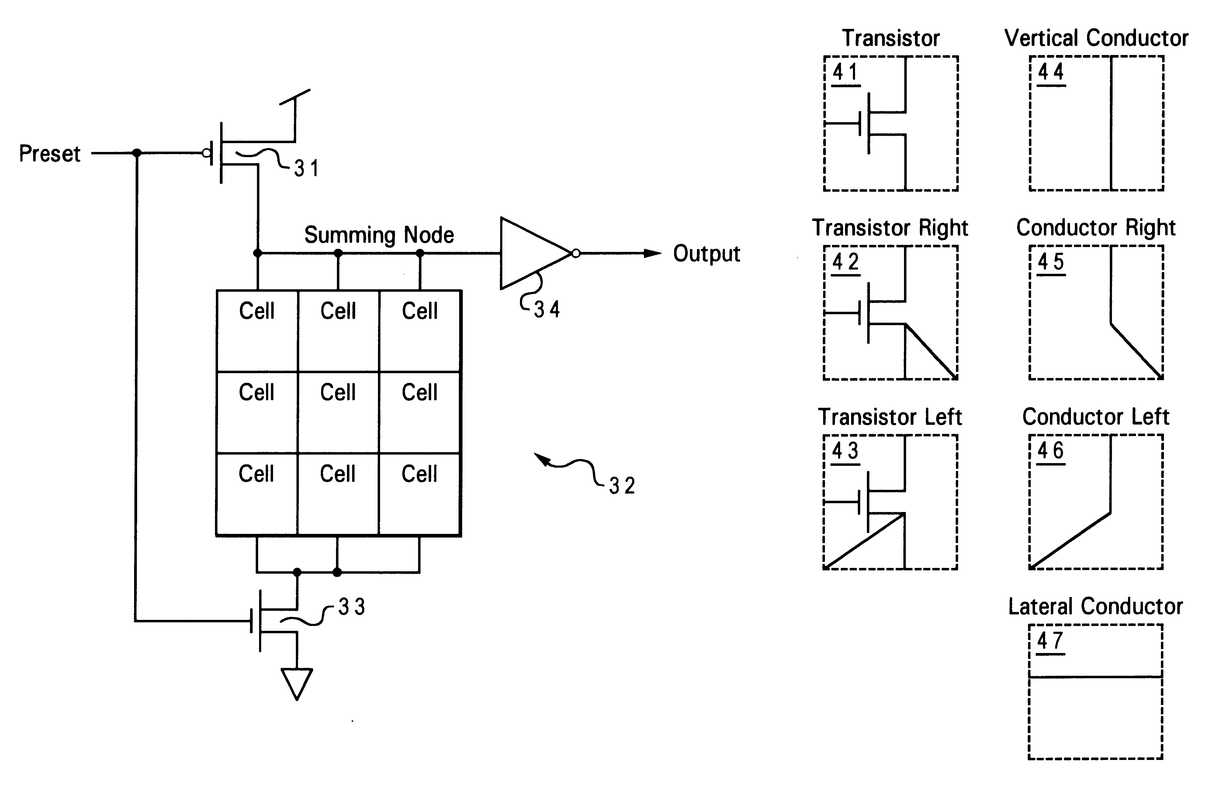
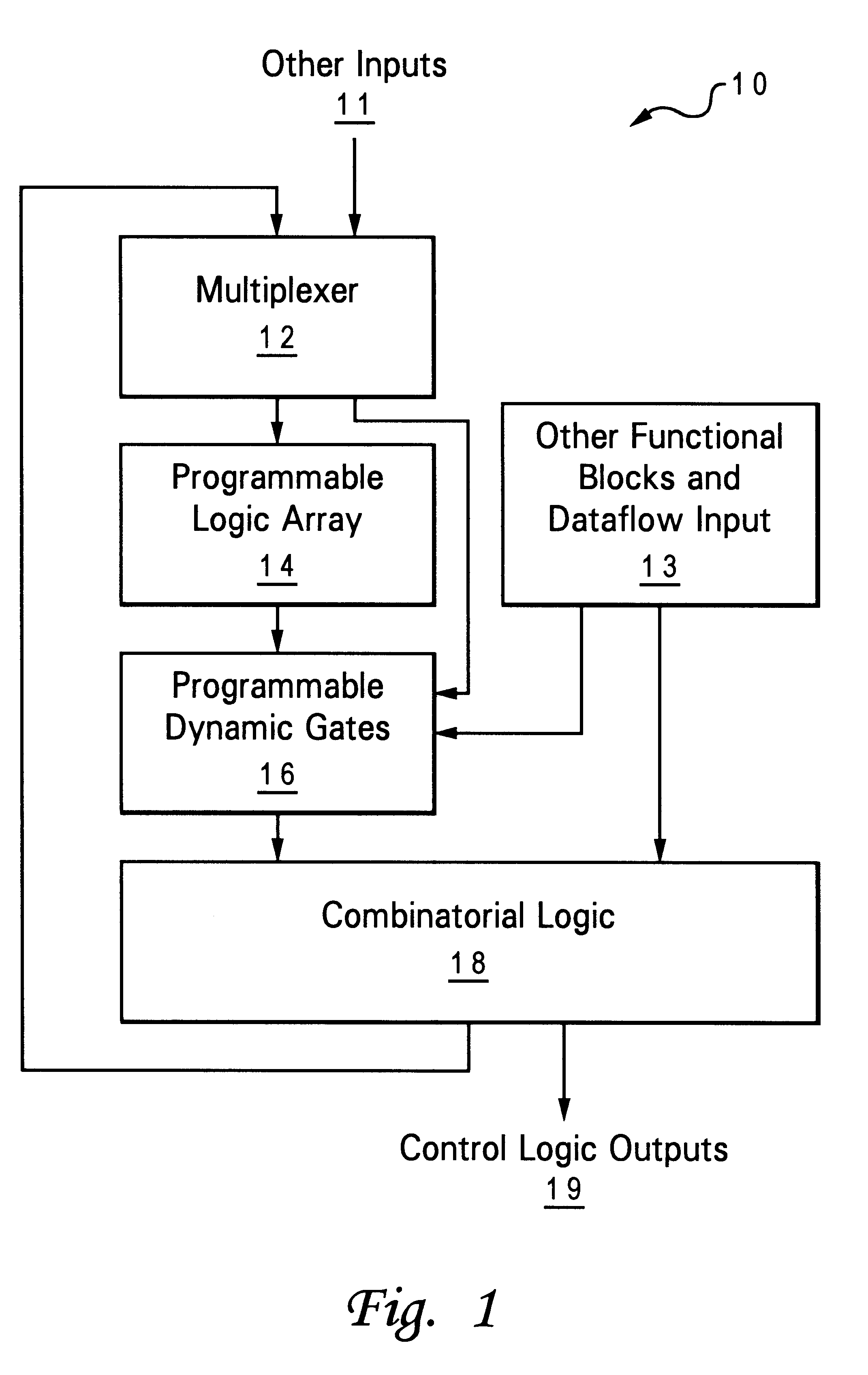
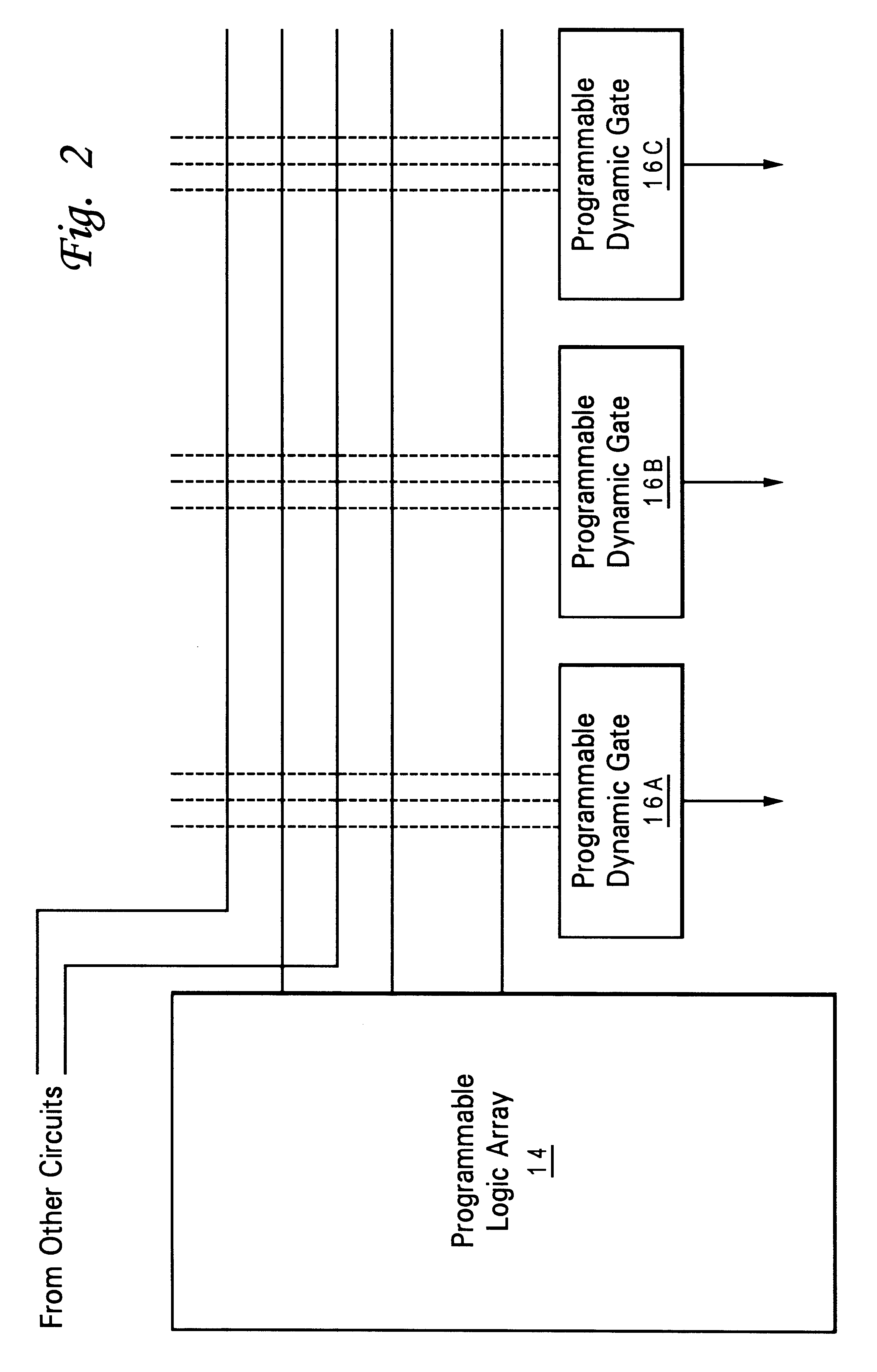
With reference now to the figures and in particular with reference to FIG. 1, there is depicted a control logic block 10 for a microprocessor that includes programmable dynamic gates 16 in accordance with an embodiment of the present invention. A multiplexer 12 selects an output of combinatorial logic 18, or other inputs 11 to provide a next-state input to a programmable logic array 14. The output of programmable logic array 14 is connected to programmable dynamic gates 16, and the output of programmable dynamic gates 16 are provided to the inputs of combinatorial logic 18 which provides control logic outputs 19 for the microprocessor block. Other inputs are provided to programmable logic gates 16 from other functional blocks and dataflow input 13 and multiplexer 12, so that operation of the logic may be dependent on these inputs without overly complicating the programmable logic array 14. Without programmable dynamic gates 16, programmable logic array 14 may not be able to efficien...


PUM


Abstract

A method and apparatus for implementing dynamic logic with programmable dynamic logic gates acts as a complement to programmable logic arrays (PLAs) used in high-speed microprocessor designs. A matrix of selectable cells provides powerful logic functions such as AND-OR gate capability with a minimum of inputs and transistors. By using programmable logic arrays and programmable dynamic gates, the efficiency of a logic block can be dramatically improved with little added circuit area.

Description

1. Technical FieldThe present invention relates in general to programmable logic circuits, and in particular, to dynamic programmable logic gates using mask-programmable logic cells.2. Description of the Related ArtLogic circuits, particularly those used to simultaneously evaluate an equation with a large number of inputs have been implemented in a variety of architectures. A programmable logic array (PLA) is an integrated circuit device that incorporates fixed sets of AND and OR logic gates or similar functions such as NAND, NOR, XOR or XNOR with one or more interconnect planes used to create several logical combinatorial outputs from several logical inputs. The interconnect planes in a mask PLA are usually metallization layers that can be redesigned and deposited during a production run without redesigning the semiconductor layers of the device. The depositing of the mask can be performed by vapor deposition of aluminum or other metals using techniques well known in the art. The m...

Claims


Application Information

Patent Timeline
IPC IPC(8): H03K19/173H01L21/82
CPCH03K19/1736
Inventor DHONG, SANG HOONGO, HUNG CAIPARK, JAEHONGTAKAHASHI, OSAMU
Owner IBM CORP
Why Eureka
Try Eureka