Transient cache storage

a cache and storage technology, applied in the field of computer system cache architectures, can solve the problems of affecting the design/test process, and affecting the performance of the cache, so as to achieve the effect of not imposing significant costs on the processor design

Active Publication Date: 2007-06-07
MACHINES INT BUSINESS
View PDF5 Cites 25 Cited by
  • Summary
  • Abstract
  • Description
  • Claims
  • Application Information

AI Technical Summary

Benefits of technology

[0009] The present invention provides a method and apparatus for storing non-critical processor information, including such empirical and experiential information as instruction trace and branch prediction information, without imposing significant costs on a processor design. According to a preferred embodiment of the present invention, transient data are stored in the processor-local cache hierarchy (in another embodiment, a cache hierarchy shared among multiple processors is used). This is achieved by providing an additional control bit in addresses requested or supplied when operating within the processor-local cache hierarchy. In one embodiment, this additional control bit forms part of the tag used to determine whether a particular cache access has been a hit or miss in a specific cache line. In another embodiment, this bit is used to determine the equivalence class to use when performing a cache lookup.

Problems solved by technology

In some cases, useful information may become lost, as branch prediction information must be reacquired in toto.
A cost / benefit tradeoff may result, as the value of the information collected is exceeded by the area cost or design / verification costs associated with enabling the information to be collected.
In some instances, a dedicated auxiliary storage hierarchy can be introduced to store this information, but at the cost of additional silicon area and design / test complexity.
The problem with this is, however, that it precludes storing the metadata and the underlying data or instruction in the same cache structure, since the two pieces of data would have conflicting storage addresses in the cache.

Method used


Image

  • Transient cache storage
  • Transient cache storage
  • Transient cache storage

Examples


Embodiment Construction

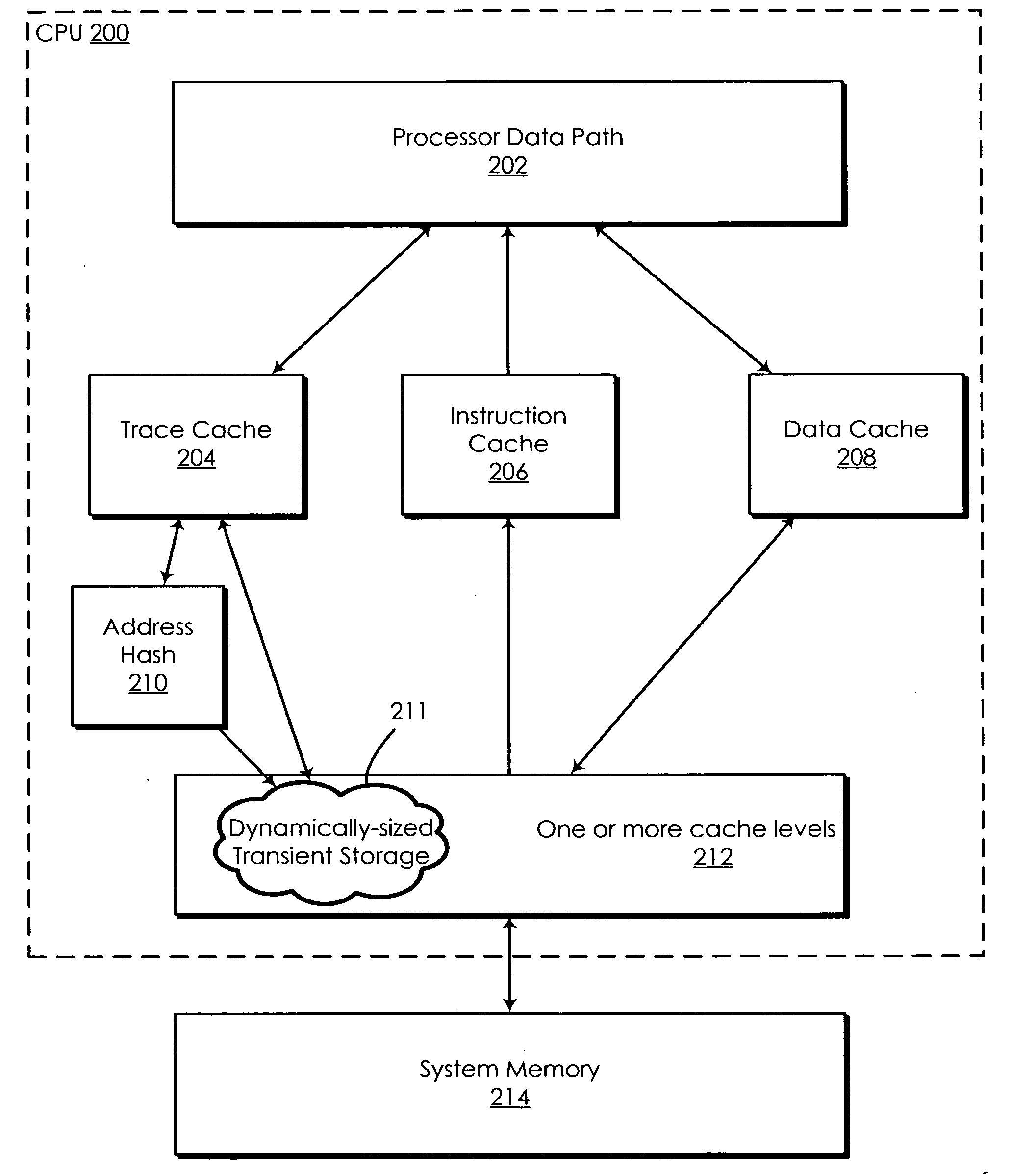
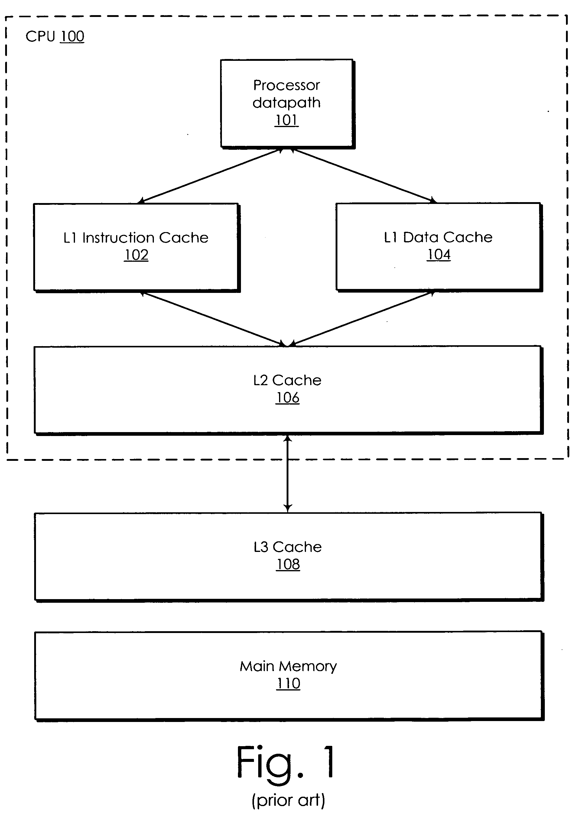
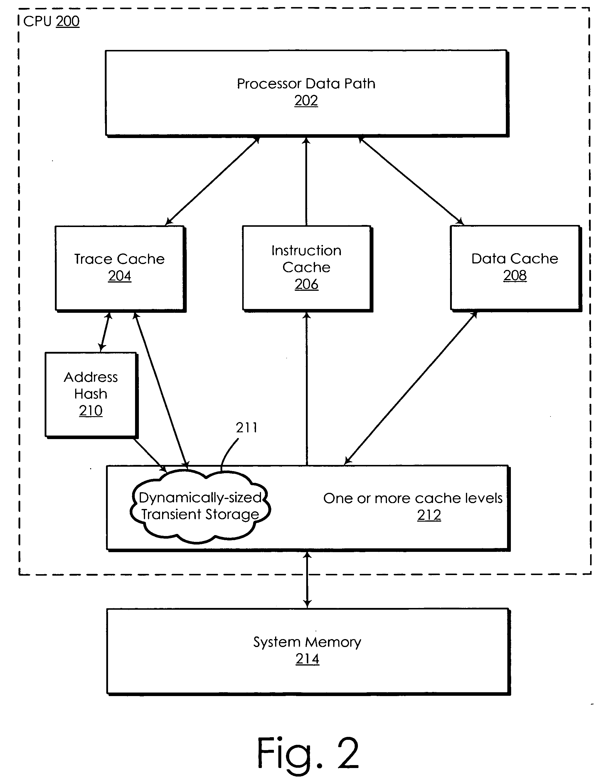
[0023] The following is intended to provide a detailed description of an example of the invention and should not be taken to be limiting of the invention itself. Rather, any number of variations may fall within the scope of the invention, which is defined in the claims following the description.

[0024]FIG. 1 is a diagram illustrating a multi-level cache architecture as may be utilized in a preferred embodiment of the present invention. Central processing unit (CPU) 100 comprises a main processor datapath 101, a Level 1 (L1) instruction cache 102, and a Level 1 (L1) data cache 104. L1 caches 102 and 104 improve the memory access performance of CPU 100 by providing quickly accessed, processor-local copies of currently in-use memory locations from which instructions are read (instruction cache 102) and data are read and written (data cache 104). Utilizing separate L1 instruction and data caches, as shown in FIG. 1, allows some of the performance benefits of a Harvard-style computer arc...


PUM


Abstract

A method and apparatus for storing non-critical processor information without imposing significant costs on a processor design is disclosed. Transient data are stored in the processor-local cache hierarchy. An additional control bit forms part of cache addresses, where addresses having the control bit set are designated as “transient storage addresses.” Transient storage addresses are not written back to external main memory and, when evicted from the last level of cache, are discarded. Preferably, transient storage addresses are “privileged” in that they are either not accessible to software or only accessible to supervisory or administrator-level software having appropriate permissions. A number of management functions/instructions are provided to allow administrator/supervisor software to manage and/or modify the behavior of transient cache storage. This transient storage scheme allows the cache hierarchy to store data items that may be used by the processor core but that may be too expensive to allocate to external memory.

Description

BACKGROUND OF THE INVENTION [0001] 1. Technical Field [0002] The present invention relates generally to the area of cache architectures for computer systems. Specifically, the present invention relates to a cache system that allows for the existence of cache lines for storing trace data and other empirical information, in which these particular cache lines are not written back to main memory. [0003] 2. Description of the Related Art [0004] Current processors generate and collect a multitude of data intended to improve performance of a computer system. This includes performance monitoring data (e.g., profile data), branch prediction data, performance monitor data, pre-decoded instruction information, branch history information, branch prediction tables, and the like. Some of this data is stored in dedicated arrays or tables (e.g., profile data tables, branch history tables, or branch target address caches), while other data is stored in conjunction with instructions in the L1 (Level ...

Claims


Application Information

Patent Timeline
Patent Type & Authority Applications(United States)
IPC IPC(8): G06F17/30
CPCG06F9/3808G06F9/3844G06F12/0802G06F12/0804G06F12/12G06F12/1491G06F12/08G06F12/00
Inventor ALTMAN, ERIK R.GSCHWIND, MICHAEL KARLMONTOYE, ROBERT KEVINRIVERS, JUDE A.SATHAYE, SUMEDH WASUDEOWELLMAN, JOHN-DAVIDZYUBAN, VICTOR
Owner MACHINES INT BUSINESS
Why Eureka
Try Eureka