Apparatus and method for optimized compression of interlaced motion images

a technology of interlaced motion and compression method, applied in the field of digital image signal processing, can solve the problems of inefficient encoding, inefficient encoding, inefficient encoding, etc., and achieve the effect of optimizing the compression of motion images and avoiding inefficiencies and inadequacies

Inactive Publication Date: 2001-09-11
QUVIS +1
View PDF15 Cites 467 Cited by
  • Summary
  • Abstract
  • Description
  • Claims
  • Application Information

AI Technical Summary

Benefits of technology

The invention provides a way to compress videos with interlaced frames more efficiently than traditional methods. This helps to avoid the problems of block-based approaches.

Problems solved by technology

The patent text discusses the problems with processing digital images that have interlaced fields. The conventional methods used for processing these images have limitations such as poor vertical correlation and inefficient encoding. The text also highlights the issues with block based compression schemes such as MJPEG and MPEG, which can generate boundaries, visual artifacts, and large local errors. Therefore, there is a need for a new digital image signal processing method that can address these problems and provide better results.

Method used


Image

  • Apparatus and method for optimized compression of interlaced motion images
  • Apparatus and method for optimized compression of interlaced motion images
  • Apparatus and method for optimized compression of interlaced motion images

Examples


Embodiment Construction

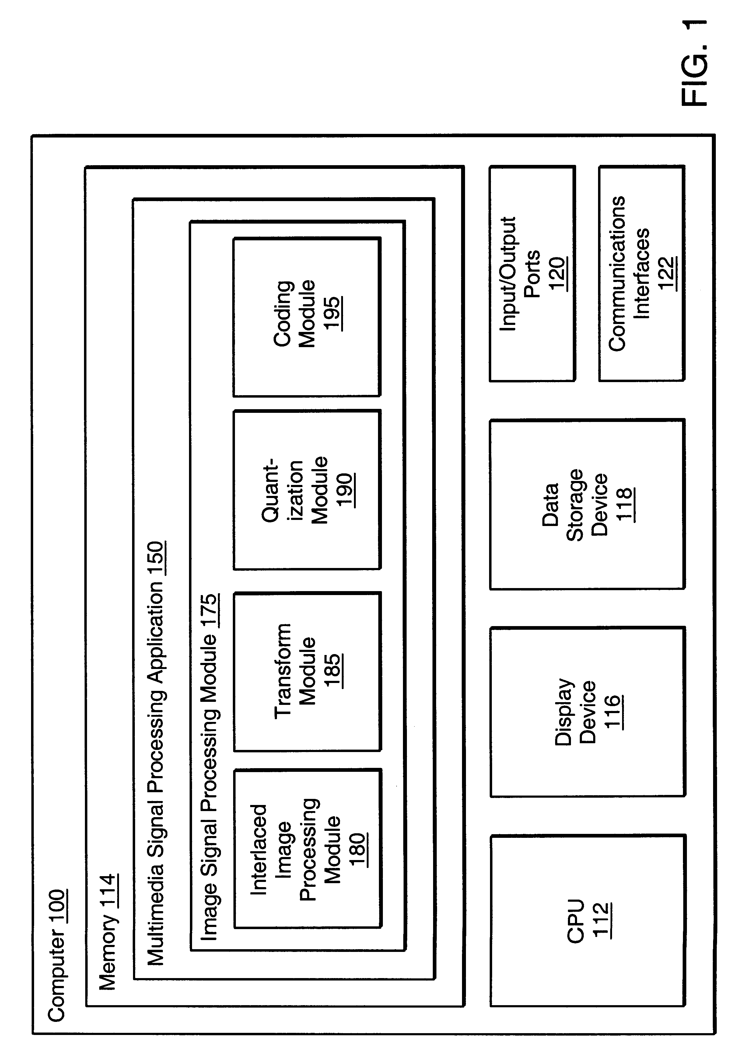
Referring now to the block diagram of FIG. 1, a computer 100 incorporating an embodiment of an interlaced image processing module 180 constructed in accordance with the present invention is shown.

The computer 100 includes a CPU 112, memory 114, display device 116, data storage device 118, input / output ports 120 and communications interfaces 122. The CPU 112 is arranged to execute instructions, such as those stored in memory 114, which may be a conventional RAM or any conventional memory for storing instructions for execution by the CPU 112. The display device 116 is conventional, such as a CRT, LCD or LED type display. Various conventional hardware for storing data may be used for the data storage device 118, such as a hard disk, or a tape drive. The input-output ports 120 are also conventional, and can be arranged to input and output video signals, such as interlaced motion image signals (e.g., NTSC broadcast television format). Although it is understood that the computer may opera...


PUM


Abstract

An interlaced image processing module and corresponding method facilitate improved processing of interlaced motion images. In one embodiment, the interlaced image processing module receives image data frames having interlaced first and second fields and produces a reference field and error field. The reference field corresponds to the still image content of the interlaced frame, whereas the error field corresponds to the motion content of the interlaced frame, particularly the motion between fields. Motion between fields is thus represented in the error field, without redundant representation of the still image content provided by the first field. Where there is little motion between fields, the error terms will be small so the predictor preserves the coding efficiency provided by any auto-correlation in the image. Further, the interlaced image processing method does not rely upon pixel group classification, and thus avoids classification errors, and the loss of coding efficiency from still image content in motion classified blocks. Finally, problems presented by relative motion between fields are avoided, as are local artifacts. Another embodiment transforms the interlaced fields into frame data having a high frequency field and a low frequency field.

Description


Claims


Application Information

Patent Timeline
Owner QUVIS
Why Eureka
Try Eureka