Oil mist generating system

a technology of oil mist and generating system, which is applied in the direction of machines/engines, combustion types, lighting and heating apparatus, etc., can solve the problems of equipment being shut down, and equipment being slowed down

Inactive Publication Date: 2001-09-18
CIRCOR RELIABILITY SERVICES CO
View PDF14 Cites 41 Cited by
  • Summary
  • Abstract
  • Description
  • Claims
  • Application Information

AI Technical Summary

Benefits of technology

The present invention comprises an improved oil mist generating system which provides an air supply, supplying a controlled source of pressured air, an oil supply for supplying a source of oil and oil mist generation means by which air and oil are combined to form oil mist for distribution through piping to the equipment to be lubricated. The system is further characterized by several improvements. The oil supply includes a main oil reservoir and an auxiliary oil reservoir. The oil mist generation means includes a main mist generator and an auxiliary mist generator connected to the main oil reservoir and the auxiliary oil reservoir, respectively. Each of the oil mist generators are c...

Problems solved by technology

For example, if the generation of oil mist is interrupted for any of a number of reasons, it may be necessary to shut the system down for repairs or adjustments to correct the situation.
This may result in periods of time when the equipment is not being lubricated.
It may even re...

Method used


Image

  • Oil mist generating system
  • Oil mist generating system
  • Oil mist generating system

Examples


Embodiment Construction

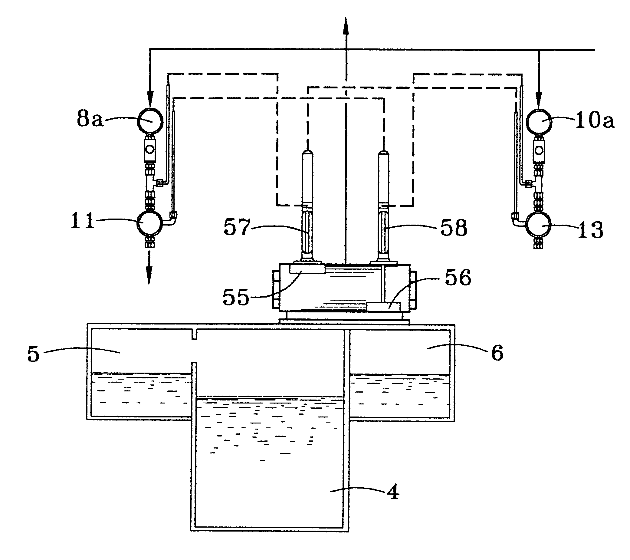
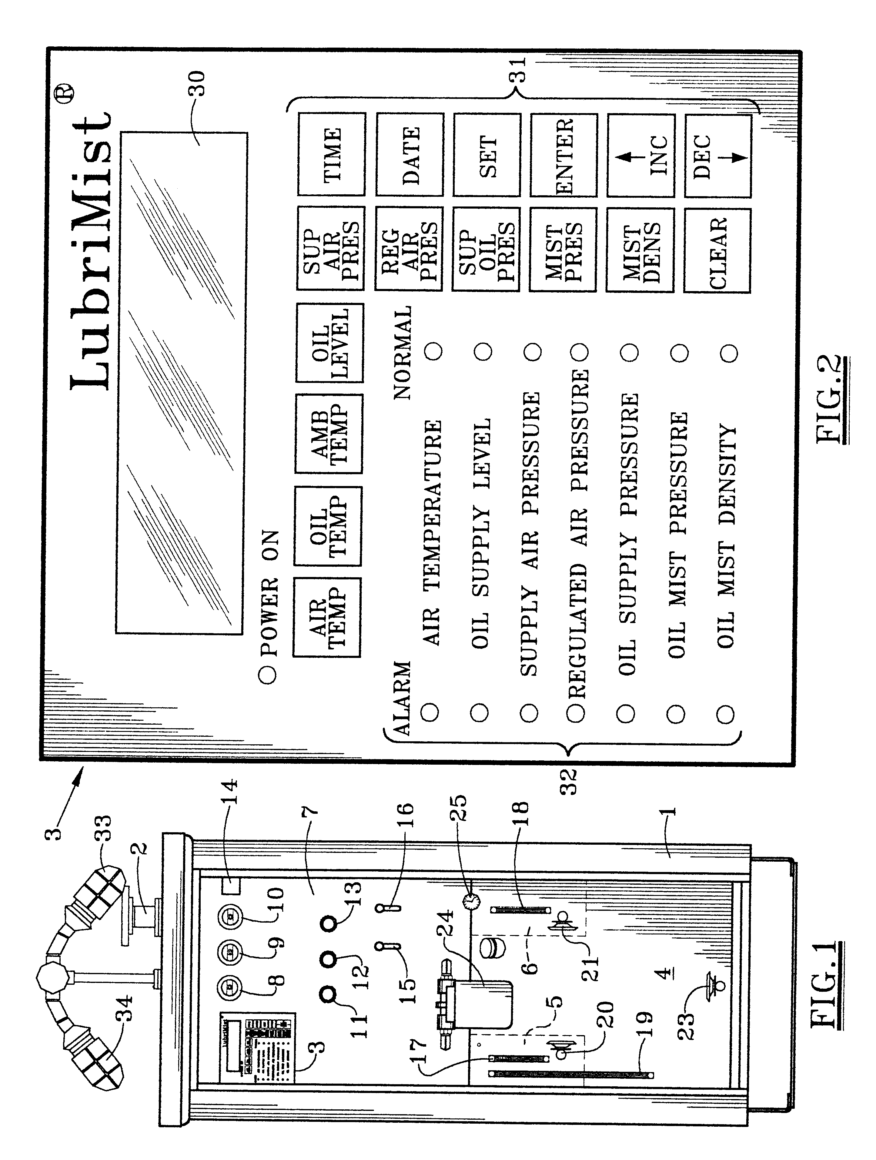
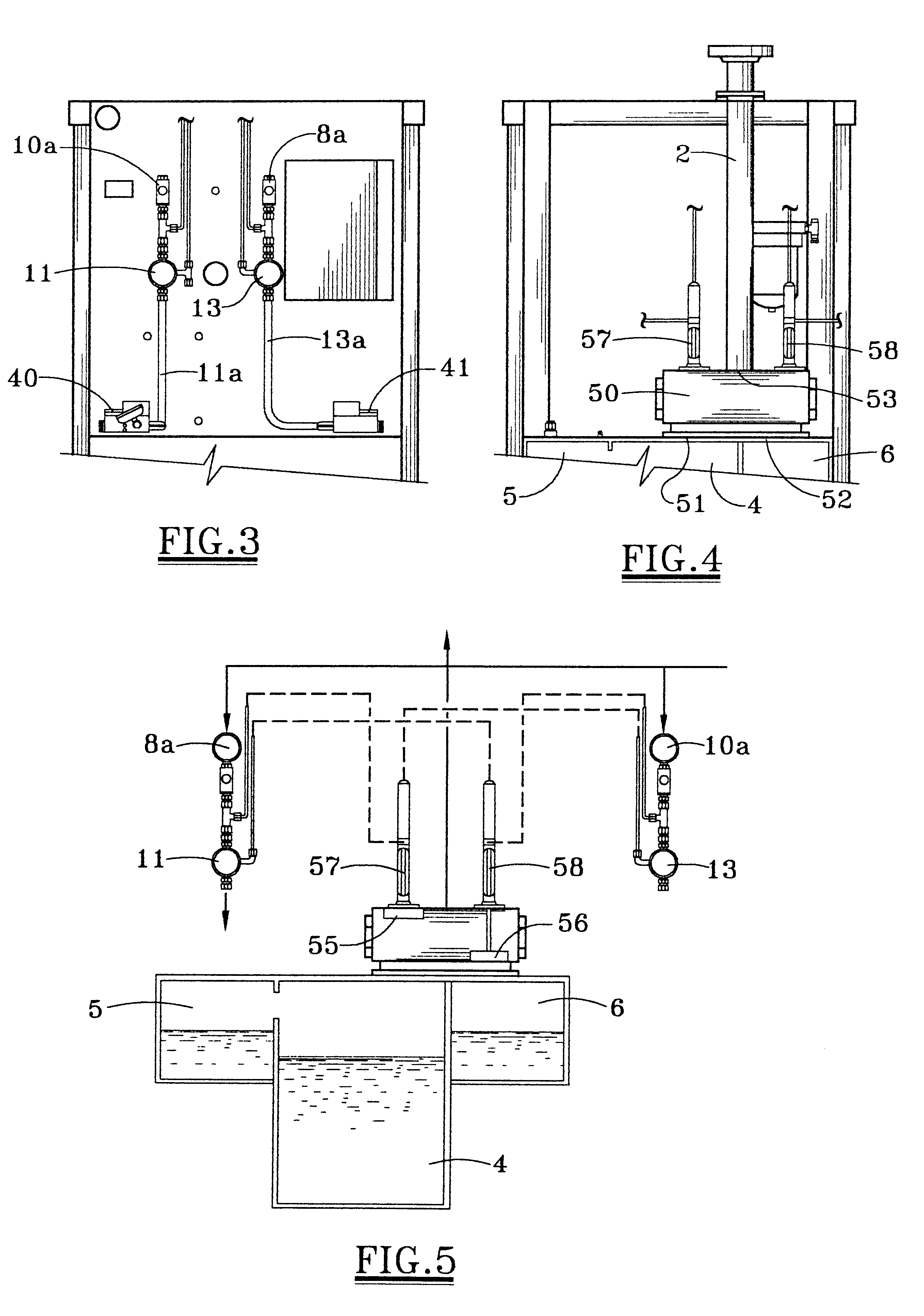
Referring first to FIG. 1, there is shown a console 1 in which the components of the improved oil mist generating system of the present invention are housed. All these components are combined to provide an air supply for supplying a controlled source of pressurized air, an oil supply for supplying a source of oil and oil mist generators connected to the air supply and the oil supply and by which air and oil are combined to form oil mist for distribution through an outlet 2 and connected piping (not shown) for distribution to the equipment (not shown) to be lubricated. The entire system is monitored and controlled by a microprocessor which monitors and controls temperature, pressure and density operating variables of the system. The monitoring and controlling is operator interfaced from a keypad and display 3 mounted on the front panel 7 of the console 1. The keypad and display 3 will be described more fully hereafter with reference to FIG. 2.

As previously stated, the console 1 house...


PUM


Abstract

An improved oil mist generating system in which air and oil are supplied to a mist generator in which the air and oil are combined to form oil mist. The system is characterized in that the oil is alternately provided by a main oil reservoir and an auxiliary oil reservoir each of which is provided with a mist generator. Each mist generator is operatively associated with a control device for alternatively activating one of the mist generators while deactivating the other. Also disclosed is an oil mist generator which includes a heater manifold extending into an oil reservoir heating both air and oil prior to entry into a mist head in which the air and oil are combined to form an oil mist. Air and oil are introduced into the mist head through plates which are removable for replacement by plates of different sizes, allowing oil mist capacity to be changed.

Description

1. Field of the InventionThe present invention pertains to lubrication systems. More specifically, the present invention pertains to lubricating systems in which lubricant is delivered in the form of oil mist to lubricate machinery bearings.2. Description of the Prior ArtOil mist lubrication is utilized in many industries to provide continuous, effective lubrication to the bearings of rotating equipment such as centrifugal pumps, electric motors, steam turbines, gear box, blowers, and fans. An oil mist lubrication system typically comprises an air supply for supplying a controlled source of pressurized air, an oil supply for supplying a source of oil and oil mist generation devices connected to the air and oil supply and by which the air and oil are combined to form oil mist for distribution through piping to the equipment. The oil mist continuously bathes the bearings of the equipment and maintains a slight positive pressure in the bearing housing to reduce contamination from outsi...

Claims


Application Information

Patent Timeline
IPC IPC(8): F16N7/32F16N7/00
CPCF16N7/32
Inventor EHLERT, CHARLES W.
Owner CIRCOR RELIABILITY SERVICES CO
Why Eureka
Try Eureka