Liquid spray cooled module

a technology of liquid spray cooling and modules, applied in the field of antennas, can solve the problems of physical limitations of rf (radio frequency) feed, the length of heat exchangers imposes some limitations on the system, and limits the optimal size of the exchanger

Inactive Publication Date: 2001-09-18
RAYTHEON CO
View PDF10 Cites 50 Cited by
  • Summary
  • Abstract
  • Description
  • Claims
  • Application Information

AI Technical Summary

Problems solved by technology

Unfortunately, the finite length of the heat exchanger imposes some limitations on the system insofar as there is a need to pump coolant therethrough same.
These considerations limit the optimal size of the exchanger.
An additional problem is due to the physical limitations of the RF (radio frequency) feed located at the back end of the stick.
Unfortunately, the T / R module is conventionally built into a small package.
Removal of heat is problematic in that the heat must be moved through several thermal / resistant layers.
The inherent inefficiencies of the electronic components causes the generation of large amounts of thermal energy, the thermal energy causes an increase in the junction temperatures of the associated components.
Differing coefficients of thermal expansion between the module and the heat exchanger will cause the expansion and contraction of the heat exchanger to damage the module and / or break a bond line therebetween.
Unfortunately, lattice spacings of active array antennas designed in accordance with conventional teachings are constrained based on the projected footprint of the T / R module, notwithstanding the desirability of more flexible lattice spacing arrangements to accommodate frequency.
In summary, there are several problems with the conventional active array antenna design including: high heat density, excessive layers of thermal resistance, physical component assembly, mounting the T / R module to the subarray, lattice spacing, and thermal mismatch.

Method used


Image

  • Liquid spray cooled module
  • Liquid spray cooled module
  • Liquid spray cooled module

Examples


Embodiment Construction

Illustrative embodiments and exemplary applications will now be described with reference to the accompanying drawings to disclose the advantageous teachings of the present invention.

While the present invention is described herein with reference to illustrative embodiments for particular applications, it should be understood that the invention is not limited thereto. Those having ordinary skill in the art and access to the teachings provided herein will recognize additional modifications, applications, and embodiments within the scope thereof and additional fields in which the present invention would be of significant utility.

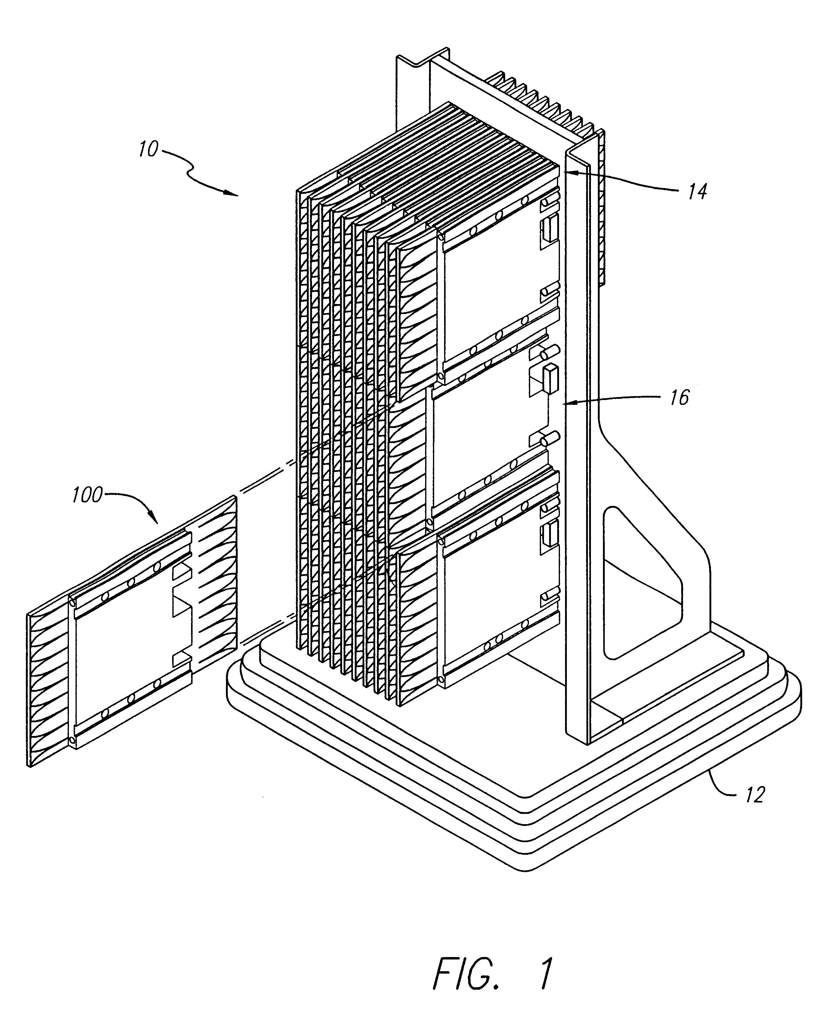
FIG. 1 is a diagram showing an assembly of T / R modules in accordance with the teachings of the present invention. The assembly 10 includes a base 12, which supports a shear panel 14. FIG. 1 shows the typical assembly / interlocking modules assembled to create a portion antenna aperture. Using this interlocking method an N.times.M array can be constructed. Approxim...


PUM


Abstract

A radar system and method of cooling same. In the illustrative embodiment, the inventive system includes a radar array comprising a circuit board; a plurality of radiating elements printed on the circuit board; and a plurality of transmit and receive modules disposed on the circuit board in communication with the radiating elements. In a specific implementation, the invention further includes means for cooling the T/R modules. In the preferred embodiment, the modules are spray cooled. A particularly novel aspect of the invention is the provision of a mechanism for physically, electrically and hydraulically interconnecting the T/R modules or modules. The physical interconnect is achieved by rails mounted on the top bottom covers and sides of the circuit boards. The rails allow for the modules to be dovetailed together and thereby secured against vertical and lateral stresses.

Description

1. Field of the InventionThe present invention relates to antennas. More specifically, the present invention relates to methods and apparatus for cooling active array radar antennas.2. Description of the Related ArtActive array antennas allow for electronic steering of a radar beam. Active array antennas include a plurality of antenna sub-arrays commonly referred to as `sticks` comprising 20 to 30 radiating elements. The stick has a finite thickness and a heat exchanger located in a central portion thereof. The heat exchanger is designed to remove heat from circuit components, particularly the transmit / receive (T / R) modules mounted on either side thereof. Unfortunately, the finite length of the heat exchanger imposes some limitations on the system insofar as there is a need to pump coolant therethrough same. In addition, the heat exchanger imposes the more general requirements of fabrication, installation and removal. These considerations limit the optimal size of the exchanger.An a...

Claims


Application Information

Patent Timeline
Patent Type & Authority Patents(United States)
IPC IPC(8): H05K7/20
CPCH05K7/20345Y10S165/908
Inventor FITZGERALD, PATRICK J.BUCZEK, STEVEN G.RUPP, FREDERICK C.CHRISTOPHER, GRACE M.
Owner RAYTHEON CO
Why Eureka
Try Eureka