Fiber optic probe and coupler assembly

a fiber optic probe and coupler technology, applied in the direction of optical elements, instruments, investigating moving fluids/granular solids, etc., can solve the problems of small scattering cross section, perturbing the source, and data obtained from a sample not always truly representativ

Inactive Publication Date: 2001-09-18
INTERNAL REVENUE SERVICE
View PDF21 Cites 50 Cited by
  • Summary
  • Abstract
  • Description
  • Claims
  • Application Information

AI Technical Summary

Benefits of technology

An important feature of the present invention is the two-part fiber optic coupler which maintains the relative axial alignment of the transmitting and receiving fibers. The coupler assembly carries at least one aligning pin (preferably at least two such pins), which is positioned so that the two portions of the coupler can be joined together in only one way, i.e. with the transmitting and receiving fibers correctly aligned. This is accomplished by forming suitably-positioned, longitudinal, spaced apart cavities in the body of the coupler, in the form of bores, peripheral notches, or a combination thereof. The cavities are dimensioned to hold corresponding aligning pins and configured so that the two portions of the coupler can be secured together with fibers correctly aligned. Here, "correctly aligned" means that the transmitting fiber (or fibers) of one portion is in optical communication with the transmitting fiber (or fibers) of the other portion; similarly, the receiving fiber(s) of one portion is in optical communication with the receiving fiber(s) of the other portion. While one aligning pin may be sufficient for purposes of carrying out the invention, two pins are preferred; three or more pins may also be useful. This feature permits precise, reproducible alignment of the transmitting and receiving optical fibers of the two coupler portions. As a result, in-line devices such as lenses, filters and the like can be installed (or replaced) as needed, as can other components of the probe, without the need for time-consuming precision alignment procedures.
Still another feature of the present invention is the aligning pin (or pins) used to align the two portions of the coupler. The pins may be of any convenient dimensions, and may have the same or different cross-sections. For example, the coupler may include two aligning pins, both having an approximately circular cross-section. Alternatively, the pins may have differently-shaped cross-sections (circular, square, hexagonal, etc.) and / or different dimensions to facilitate correct placement.
Still another feature of the present invention is the probe, which has a tip that, with the aid of the coupler, can quickly and easily be installed with the transmitting and receiving fibers precisely aligned with their counterparts in a probe body or optical cable. The tip may include a window to protect the optical fibers and other interior components of the probe from the samples being measured (and, in some cases, from harsh industrial process environments). The fibers themselves may have features such as slanted endfaces to maximize the collection of scattered light, thereby increasing the efficiency of the probe for applications where the light intensity is low.

Problems solved by technology

Data obtained from a sample is not always truly representative of the source of that sample, since the mere act of taking the sample can alter its properties; frequently, removing a sample can perturb the source as well.
A problem encountered in Raman spectrophotometry is the small scattering cross section, that is, the very low intensity of the Raman-scattered light compared to the intensity of the incident light (also termed the "exciting light").
In addition, monochromatic light transmitted by an optical fiber excites the fiber molecules, causing fluorescence and Raman scattering within the fiber itself.
Instrumentation for Raman spectrophotometry is costly and delicate, requires high-precision, high-maintenance optical components, and is not well suited for use in many industrial process environments.
Conventional techniques for aligning the filters and optical fibers--and maintaining them in alignment--tend to be difficult and time-consuming to implement.
The probes are expensive and delicate, rendering them unsuitable for most field installations.
In part because of these problems, in part because other needed instruments were large, complex, and expensive, Raman spectrophotometry has historically been confined to research laboratories.

Method used


Image

  • Fiber optic probe and coupler assembly
  • Fiber optic probe and coupler assembly
  • Fiber optic probe and coupler assembly

Examples


Embodiment Construction

In the following description, reference numerals are used to identify structural elements, portions of elements, or surfaces in the drawings, as such elements, portions or surfaces may be further described or explained by the entire written specification. For consistency, whenever the same numeral is used in different drawings, it indicates the same element, portion, surface and area as when first used. As used herein, the terms "horizontal," "vertical," "left," right," "up," "down," as well as adjectival and adverbial derivatives thereof, refer to the relative orientation of the illustrated structure as the particular drawing figure faces the reader.

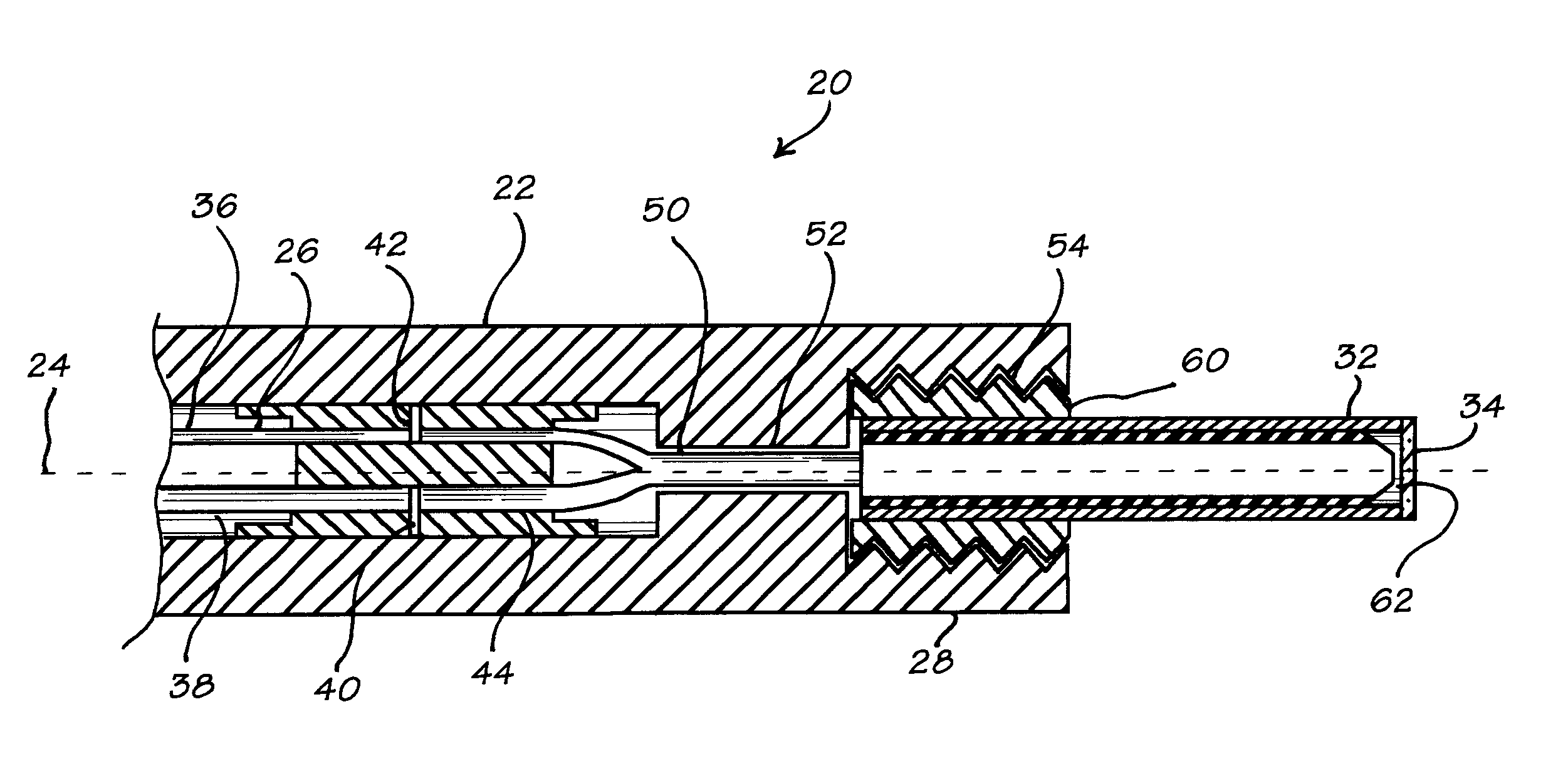
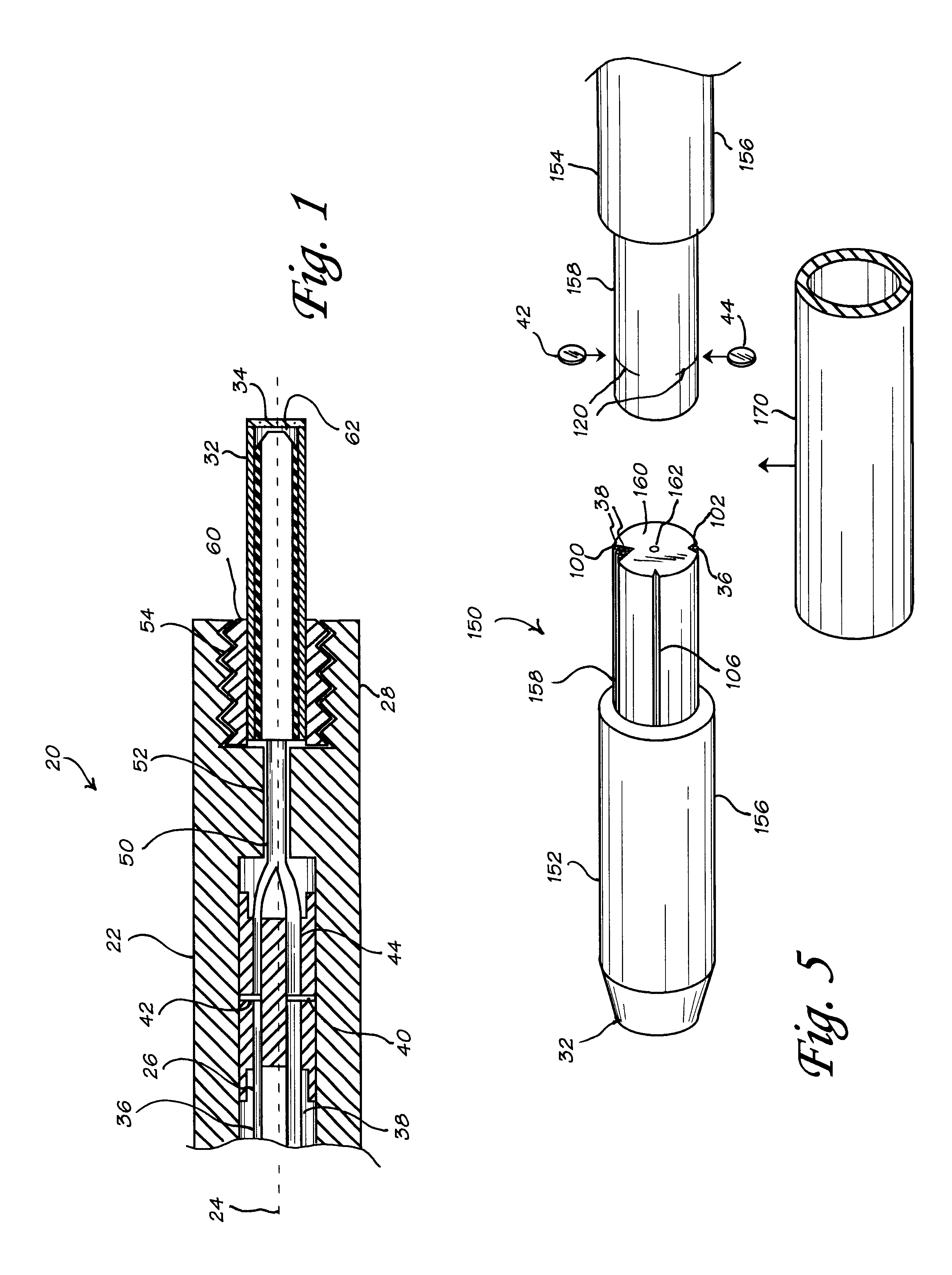
Referring now to FIG. 1, there is shown a cross-sectional view of a fiber optic probe 20 according to a preferred embodiment of the present invention. Probe 20 includes a probe body 22 with a longitudinal axis 24, an interior 26, a proximal end 28, and a probe tip 32 with a window 34. At least one light-transmitting fiber 36, at least o...


PUM

PropertyMeasurementUnit
core diametersaaaaaaaaaa
bevel angleaaaaaaaaaa
temperaturesaaaaaaaaaa

Abstract

A fiber optic probe and optical coupler assembly, and methods for making the assembly and reproducibly aligning a plurality of optical fibers therein. The coupler is used with a probe that includes a housing or probe body, a probe tip, at least one light-transmitting fiber, at least one light-receiving fiber spaced apart from the light-transmitting fiber, and (if desired), in-line devices such as filters and lenses positioned in optical communication with the fibers. The coupler includes at least one aligning pin that helps maintain the transmitting and receiving fibers in precise, reproducible relative alignment therein; thus, the coupler can be cut to install filters and other in-line devices, then readily re-assembled for use with the cut ends precisely and accurately realigned. The coupler is simple and rugged, and can be manufactured and assembled without the need for high-precision machining or optical alignment procedures.

Description

1. Field of the InventionThe present invention relates to fiber optic probes for spectrophotometry. In particular, the present invention relates to a rugged, mechanically stable coupler assembly for fiber optic probes, and to methods for making the assembly and aligning a plurality of optical fibers therein.2. Discussion of BackgroundRecent developments in fiber optics, coupled with the availability of multichannel array-type spectrometers and multiplexing technology, have generated renewed interest in the use of remote spectroscopic techniques for in-line monitoring and process control, environmental monitoring, and medical applications. Signal transmission via optical fibers allows the placement of sensitive equipment in locations remote from industrial process streams, making remote sensing particularly attractive in harsh environments. Multiplexing--the capability of transmitting signals from a plurality of sources to a single instrument--facilitates the efficient use of complex...

Claims


Application Information

Patent Timeline
Patent Type & Authority Patents(United States)
IPC IPC(8): G02B6/00G02B6/36G01N21/85G02B6/04G02B6/24G02B6/34
CPCG01N21/8507G02B6/241G02B6/04G02B6/29368G02B6/29361
Inventor O'ROURKE, PATRICK E.TOOLE, JR., WILLIAM R.
Owner INTERNAL REVENUE SERVICE
Why Eureka
Try Eureka