Moisture management system

a moisture management system and moisture management technology, applied in the direction of condensed water draining off, snow traps, heat insulation, etc., can solve the problems of constant water damage, infiltration of rainwater, and inability to apply foaming siding to the exterior of buildings, and achieve the effect of improving the adhesion of sealants and adhesives

a moisture management system and moisture management technology, applied in the direction of condensed water draining off, snow traps, heat insulation, etc., can solve the problems of constant water damage, infiltration of rainwater, and inability to apply foaming siding to the exterior of buildings, and achieve the effect of improving the adhesion of sealants and adhesives

US6293064B1Inactive Publication Date: 2001-09-25PLASTIC COMPONENTS

Image

  • Moisture management system
  • Moisture management system
  • Moisture management system

Examples


Embodiment Construction

The invention described herein is similar to that described in U.S. patent application Ser. No. 08 / 807,655 filed Feb. 27, 1997 which application is hereby referred to and incorporated by reference herein.

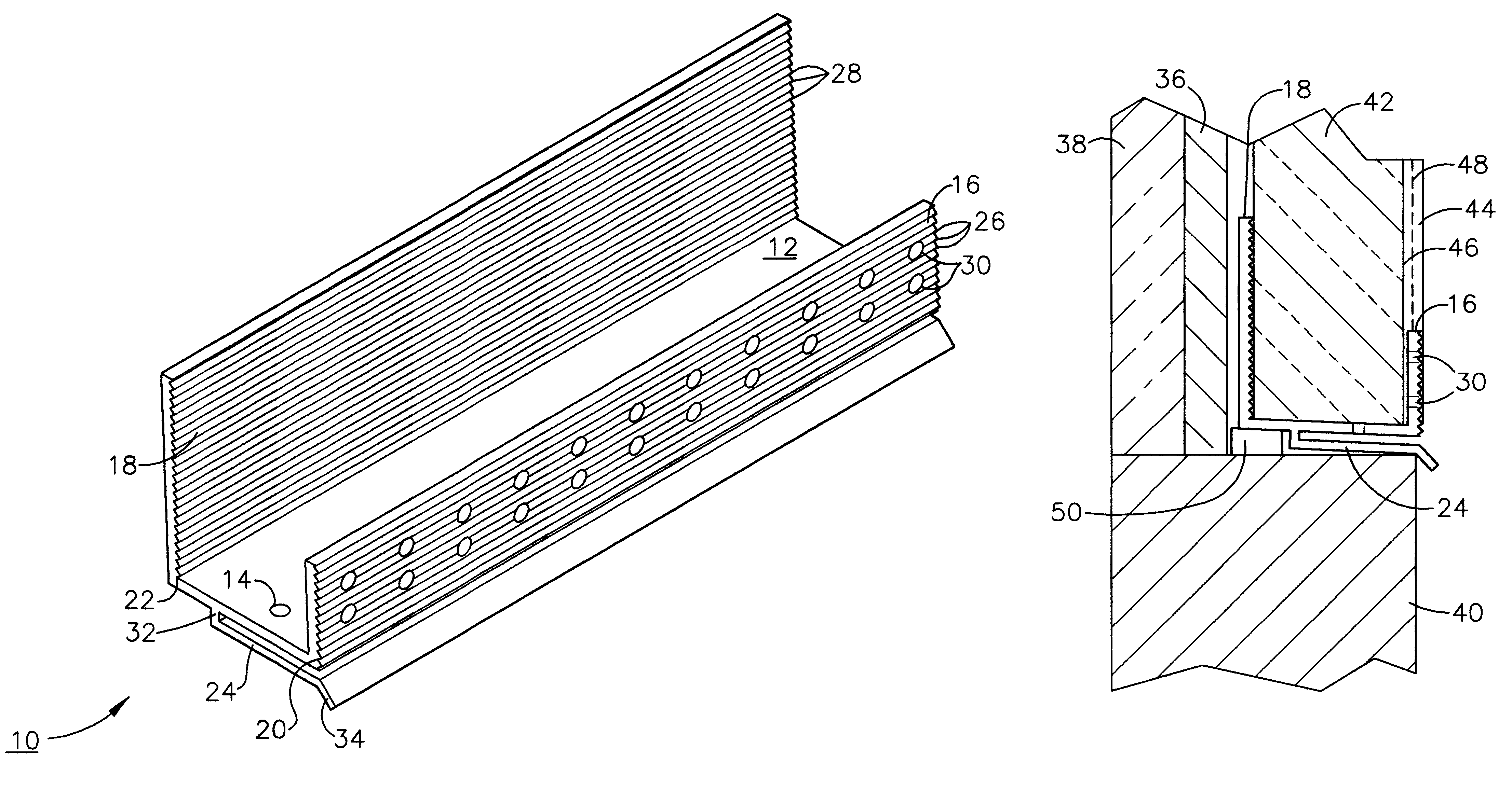
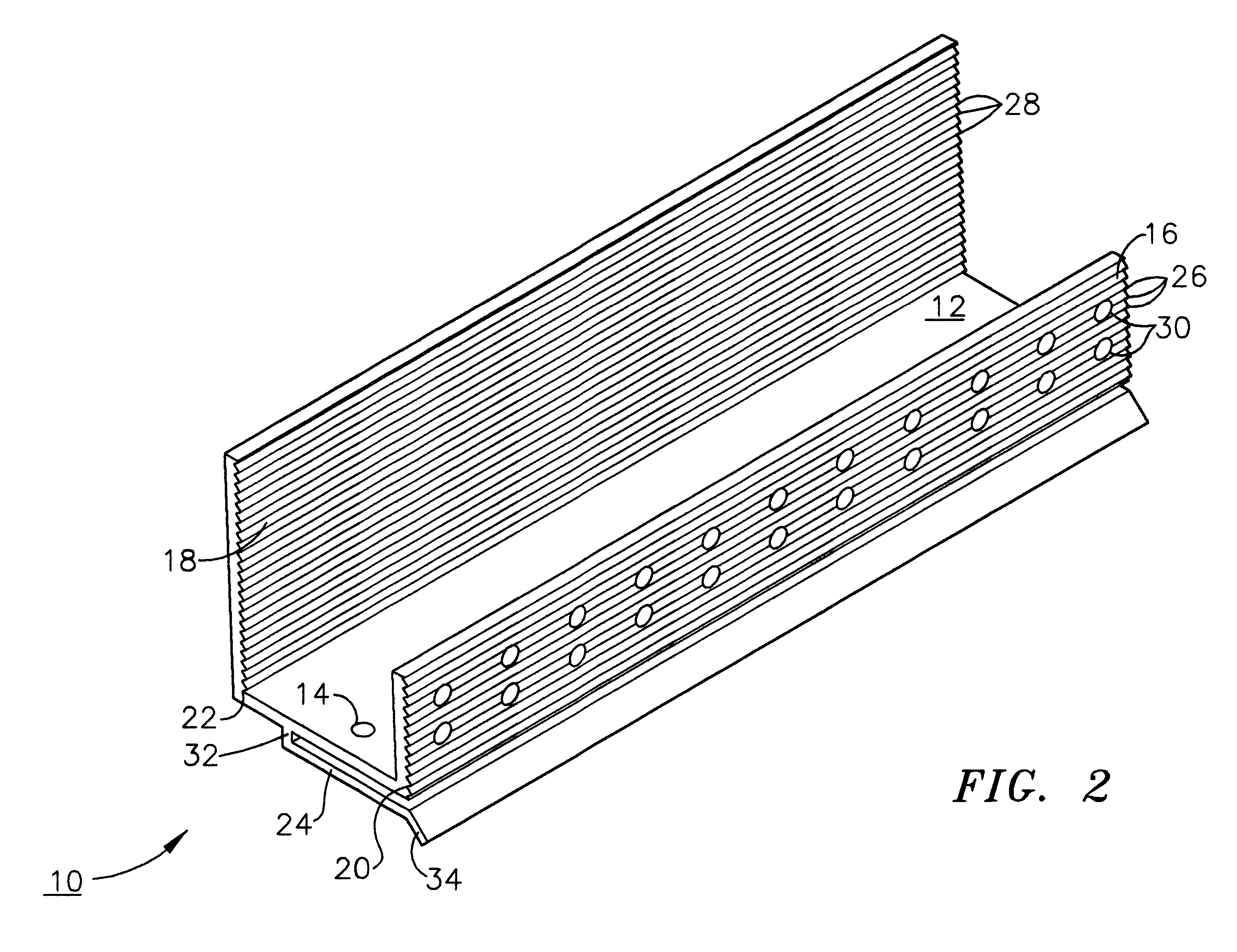
As shown in FIG. 2, the moisture management system 10 of the present invention comprises an elongated, generally U-shaped, channel having a base 12 including weep holes 14 therein, an upstanding front wall 16 and an upstanding rear wall 18 extending in parallel relationship from elongated edges 20 and 22 of base 12, and drip plate 24 integrally formed with base 12 and extending angularly downward therefrom. The front of both upstanding front wall 16 and rear wall 18 include parallel striations 26 and 28 across their entire length. Front upstanding wall 16 further includes holes 30 therein. The purpose and utility of these various features will be explained in greater detail in connection with the manner of installation of moisture management system 10.

Of particular interest and adva...


PUM


Abstract

A moisture management system for installation over doors and windows in buildings that included exterior, stucco-covered, curtain walls comprising an integrally formed, three sided, elongated track including a base having weep holes therein, an upright front wall and an upright rear wall at opposing elongated edges of the base, and, extending angularly downward from the outside of the base, and integrally formed therewith, a drip plate that permits ready drainage of water entering the moisture management system through the weep holes in the base. Elongated striations in the front faces of both the front and rear upright walls as well as holes in the front upright wall provide adherence of sealants and adhesives used in the installation process.

Description

The present invention relates to moisture management systems for use over windows, doors and other building openings on buildings where so-called stucco covered, curtain type foamed siding is applied to the exterior of a building. Such moisture management systems inhibit the infiltration of water into the building at the top of such openings by providing a path for the potentially infiltrating water to take away from the surface of the building. The moisture management system described herein is also useful at the base of such exteriorly applied foamed siding to prevent water infiltration.The infiltration of water into buildings and other structures particularly at the top of windows, doors etc as well at the base of so-called stucco-covered, curtain type, foamed siding applied to the exterior of buildings is a constant problem in both new and retrofit construction.The term curtain wall refers to a type of building construction in which an exterior non-load-bearing wall is supported...

Claims


Application Information

Patent Timeline
25 Sep 2001
Publication
US6293064B1
IPC
E04B1/76; E04F19/02; E04F13/08; E04F13/06
CPC
E04B1/762; E04B1/765; E04F13/06; E04F13/068; E04F2013/063; E04F19/02; E04F2013/065; E04F13/08
Inventors
LARSON, JOHN A.