Fuel injection system

a fuel injection system and fuel injection technology, applied in the direction of machines/engines, electric control, positive displacement liquid engines, etc., can solve the problems of inability to control the opening time of the injector valve with infinite precision, reduce the burn efficiency and thus the overall engine efficiency and emissions benefits, and achieve the effect of reducing the burn efficiency

Inactive Publication Date: 2001-09-25
YAMAHA MOTOR CO LTD
View PDF18 Cites 12 Cited by
  • Summary
  • Abstract
  • Description
  • Claims
  • Application Information

AI Technical Summary

Problems solved by technology

A problem associated with this valve is that the range of opening time of the valve of the injector cannot be controlled with infinite precision.
On the other hand, this solution has the att

Method used


Image

  • Fuel injection system
  • Fuel injection system
  • Fuel injection system

Examples


Embodiment Construction

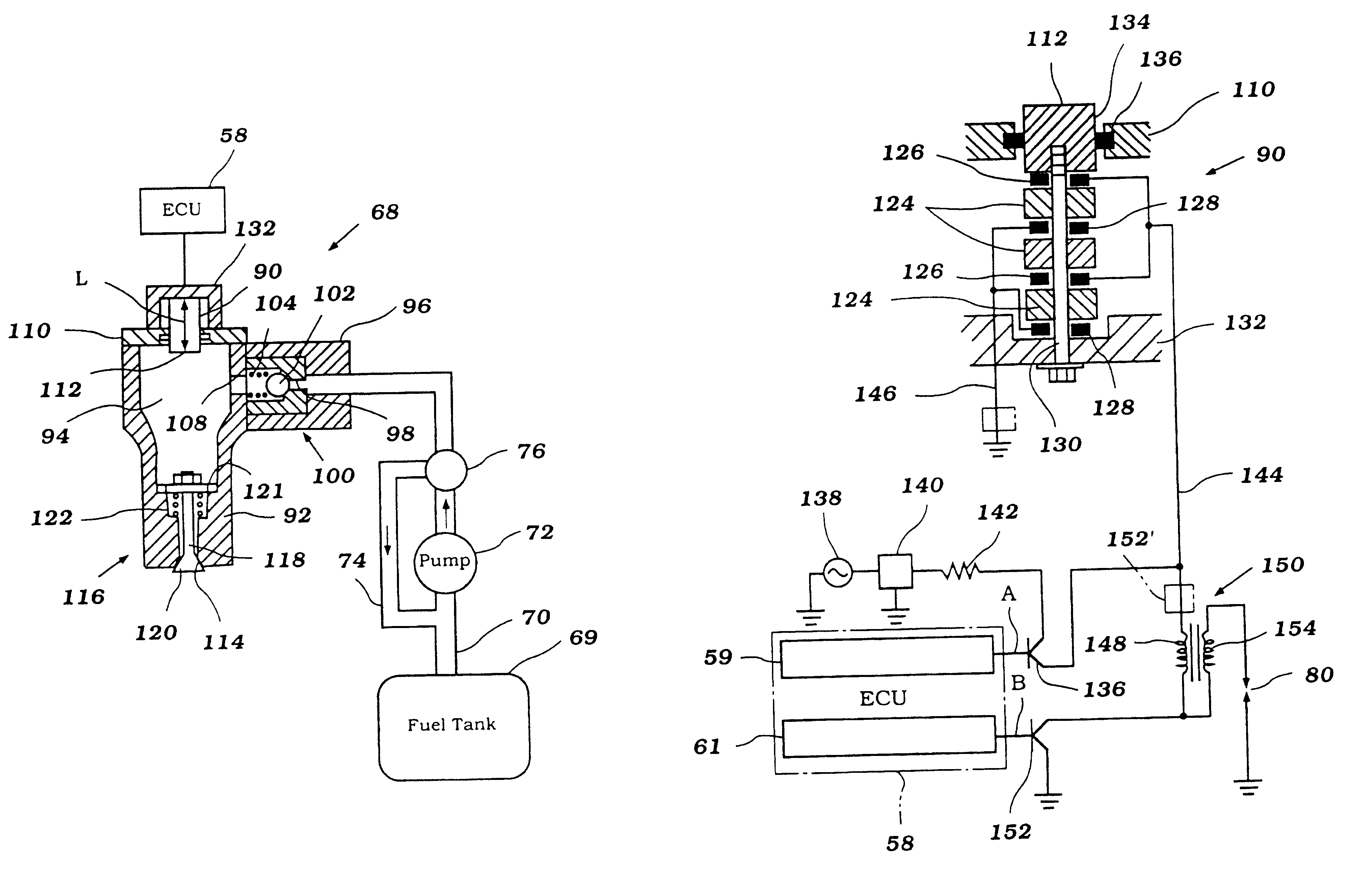
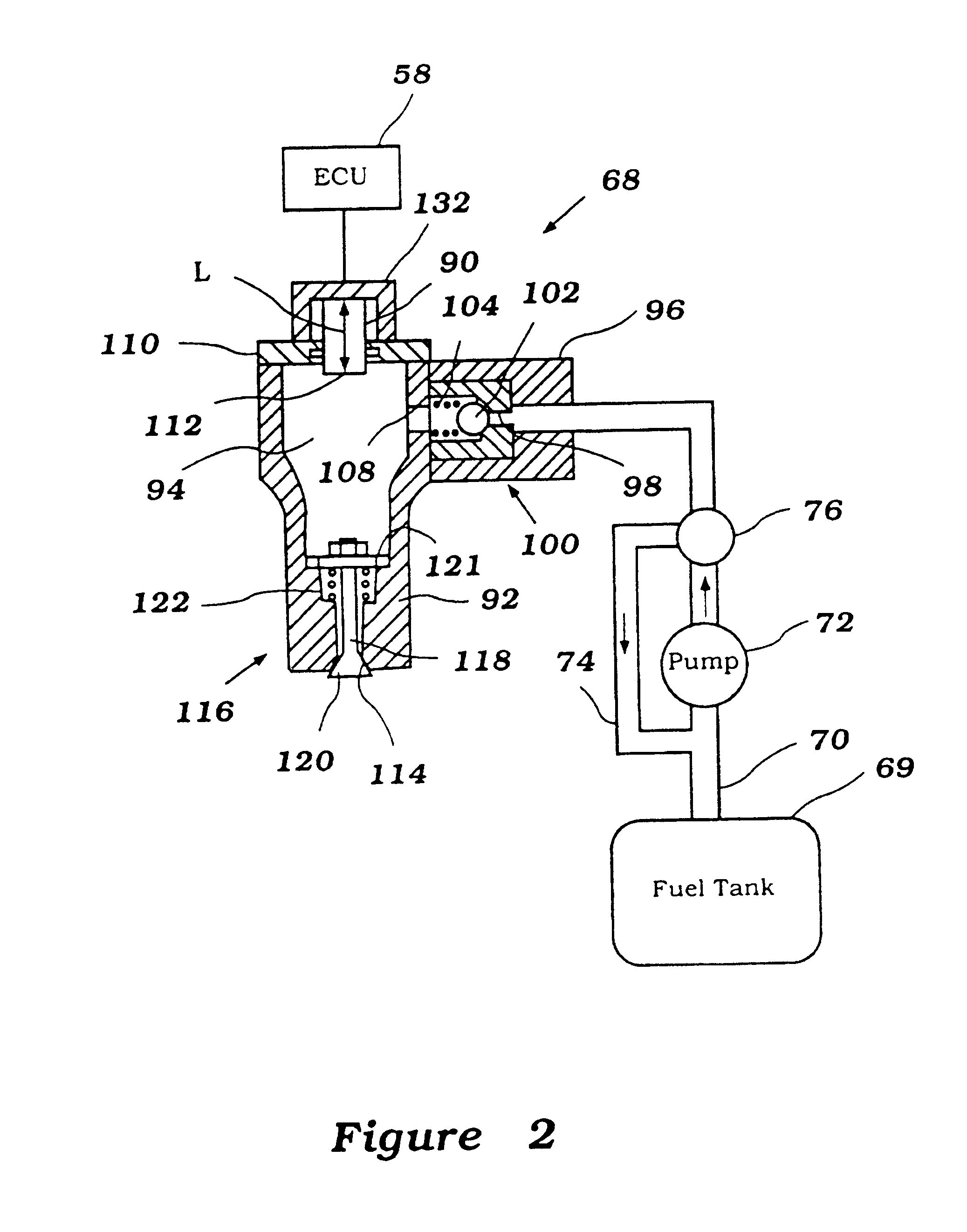
In general, the present invention is an injection system for controlling the injection of a liquid such as fuel. The invention is described for use with an internal combustion engine since this is an application for which the injection system has particular utility.

Those of skill in the art will appreciate that the injection system has utility in a variety of other applications and for use in injecting a variety of other liquids, such as oil, ink or the like.

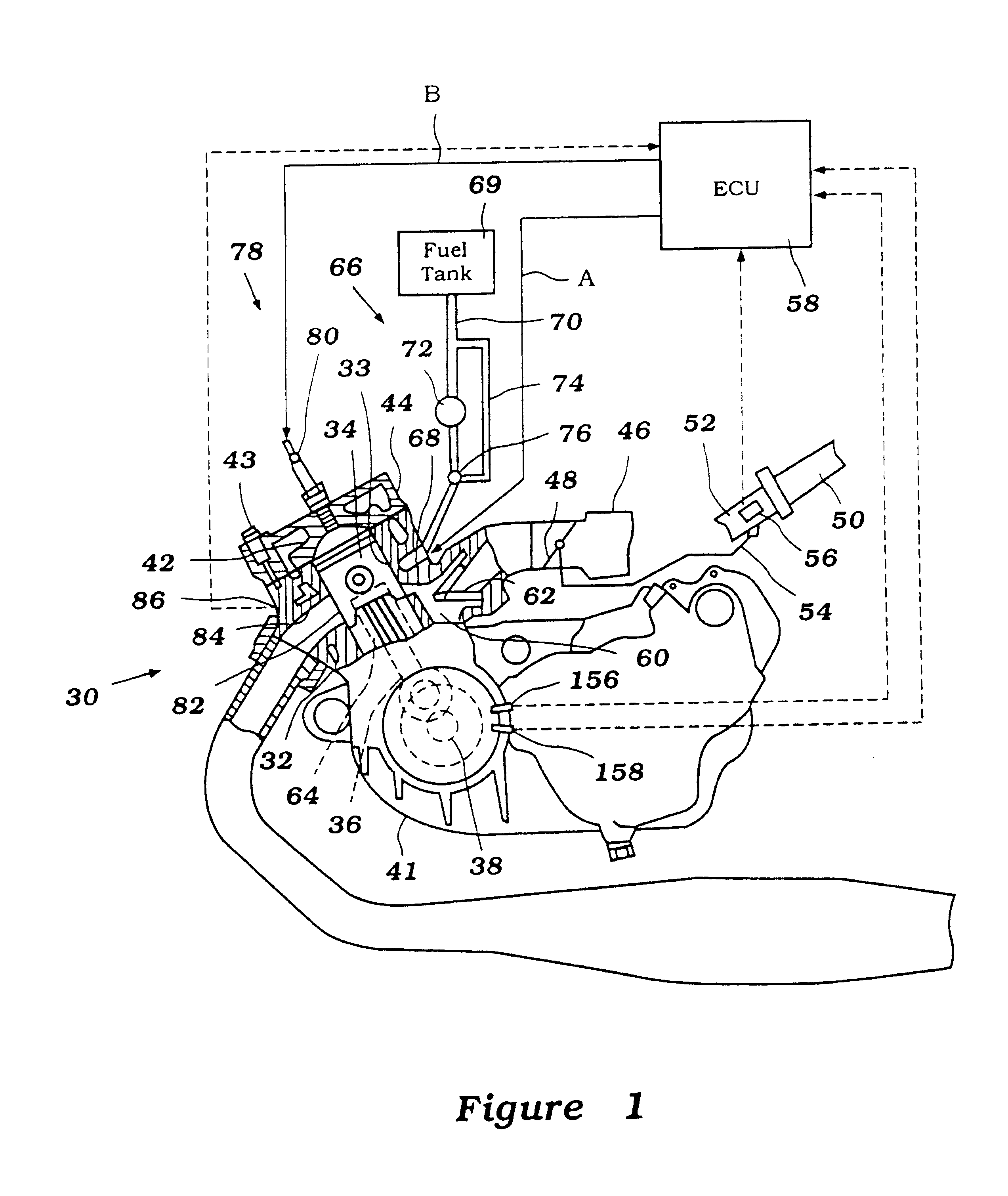
Referring to FIG. 1, an engine 30 is shown as only having only a single cylinder, and in partial schematic cross-section, with certain auxiliary components also shown partially schematically and / or in cross-section. It will be readily apparent to those skilled in the air however, how the invention may be utilized in conjunction with engines having other cylinder numbers and other cylinder configurations.

The engine 30 illustrated is depicted as arranged to operate on a two-cycle principle. Again, however, the invention may be uti...


PUM


Abstract

The present invention is an injection system including an injection device. The injection device includes a pumping chamber and an electrically operated device associated with the pumping chamber which, when energized, is capable of providing a rapid increase in localized fluid pressure in said pumping chamber without reciprocating a piston in a cylinder bore. A discharge port associated with the pumping chamber permits discharging of fluid displaced by the localized pressure increase. The injection system includes a circuit providing an energizing voltage to the electrically operated device, and a control for changing at least one characteristic of the energizing voltage selected from the group consisting of: the peak energizing voltage, the rate at which said energizing voltage increases, the rate at which said energizing voltage decreases, the duration of energization, and the frequency of energization.

Description

This invention relates to a fuel injection system, and more particularly to an injection system, which provides improved injection volume and timing control.BACKGROUND OF TE INVENTIONRecently a great deal of attention has been given to the level of emissions generated by internal combustion engines, as well as their efficiency. In order to increase the efficiency of these engines and reduce their harmful emissions, fuel injectors have been developed for metering the fuel supplied to the engine.In general, these fuel injectors include a body having a solenoid operated flow valve. Biasing means such as a spring apply a force to a body of the valve for closing the valve, while when activated the solenoid overcomes the spring force to open the valve.Fuel is supplied under high pressure to the fuel injector, such as with a high pressure pump. When the valve of the injector is opened, the fuel flows therethrough to the engine.A problem associated with this valve is that the range of openi...

Claims


Application Information

Patent Timeline
IPC IPC(8): F02M63/00F02D41/20F02D37/00F02M57/00F02D37/02F02M57/02F02M63/06F02M51/06F02B61/02F02B61/00F02D41/04H01L41/09H01L41/12
CPCF02B61/02F02D37/02F02D41/2096F02M51/0603F02M57/027F02M63/06F02D2041/2034F02M2200/21F02D2041/2051
Inventor OTOME, KIMITAKEKAKU, JUNICHIKAGEYAMA, HIDETOSHI
Owner YAMAHA MOTOR CO LTD
Why Eureka
Try Eureka