Valve

Inactive Publication Date: 2001-09-25
ITW NEW ZEALAND
View PDF22 Cites 15 Cited by
  • Summary
  • Abstract
  • Description
  • Claims
  • Application Information

AI Technical Summary

Benefits of technology

In a preferred embodiment the housing and valve head are configured so that the valve head may be "snap fitted" into the housing and retained in place within the four engagement indentations. This "snap fitting" assembly allows a valve assembly to be constructed from two elements only, and does not require add

Problems solved by technology

a) the number of separate tools required in the manufacturing process, increasing the capital start up costs for the manufacturer and associated manufacturing costs, and
b) a slow down in the manufacturing process time as a large number of components need to be firstly formed and finished and then assembled together to form the finished product, and
c) an increase in the amount o

Method used


Image

  • Valve
  • Valve
  • Valve

Examples


Embodiment Construction

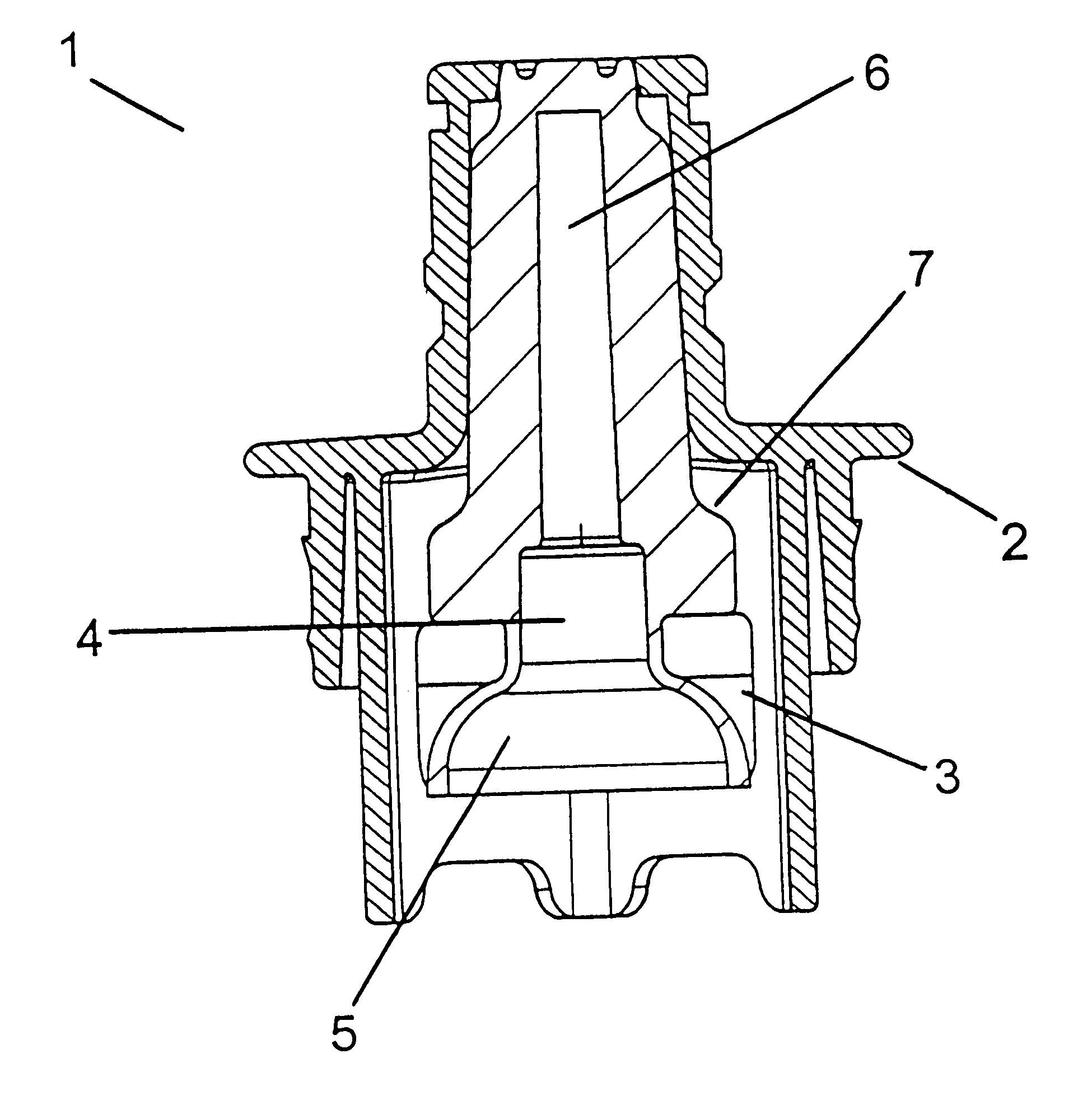
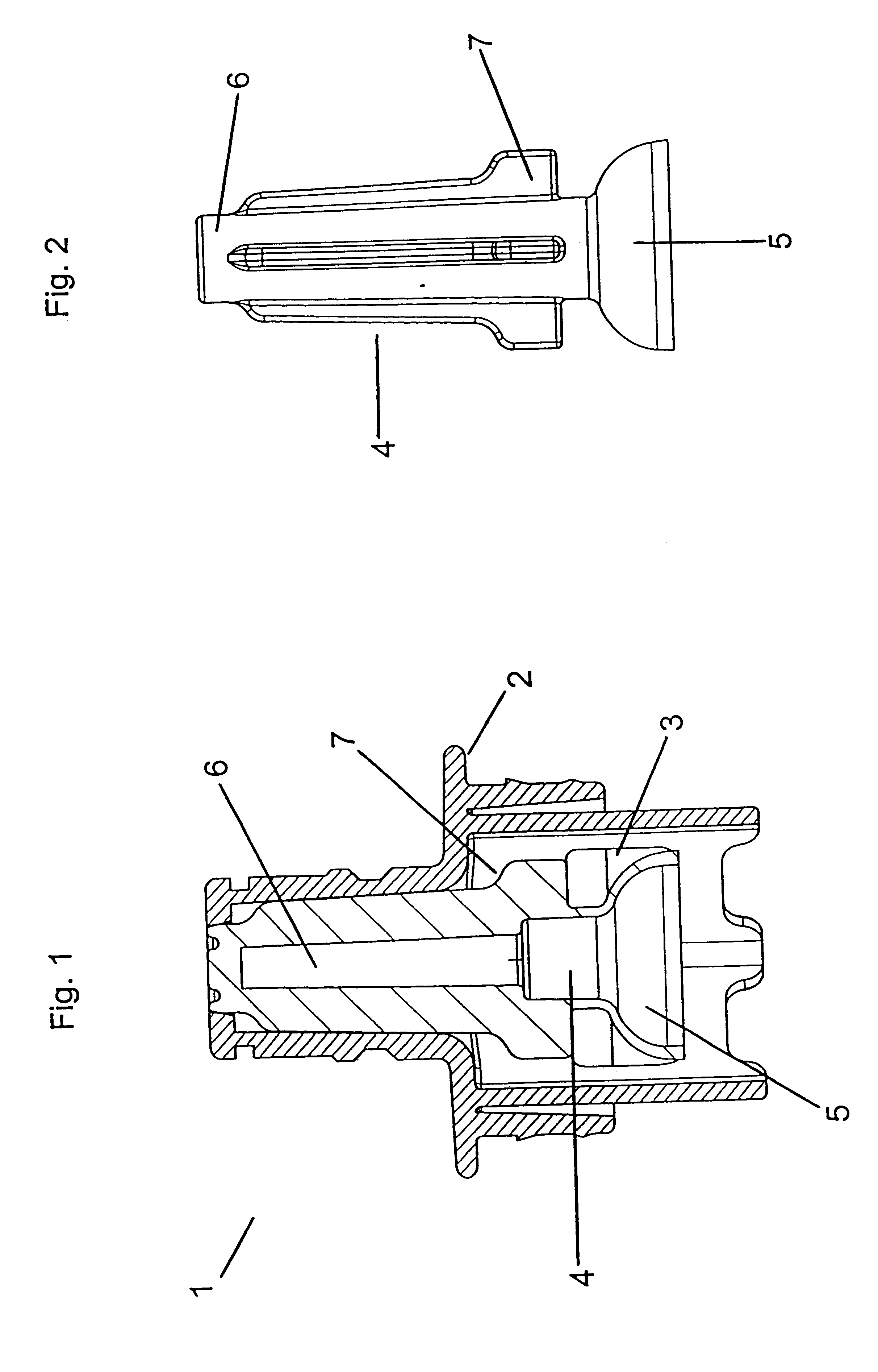
FIG. 1 illustrates a cross-sectional view of the present invention as in one embodiment.

FIG. 1 shows a cross-sectional view of a valve assembly 1. The valve assembly 1 includes a housing 2, a number of engagement indentations 3 located within the housing 2, and a valve head 4.

The valve head 4 consists of an elastically deformable cup 5 and a stem 6. Associated with the valve head stem 6 are protrusions 7 that limit the travel of the valve head 4 down the body of the valve assembly housing 2.

As can be seen from FIG. 1 the valve head cup 5 is locked in place inside the engagement indentations 3.

When in use the valve stem 6 is driven into the housing 2 causing the cup 5 to run into the edges of each indentation 3.

The force applied to the valve head stem 6 will cause the cup 5 to deform when it runs up against the edges of the indentations 3. When the cup 5 deforms fluid from a fluid port above the cup 5 (not shown) can then flow past the deformed sides of the cup and out the channel lo...


PUM


Abstract

The present invention is capable of engagement with a fluid port and capable of being open to create a fluid path, where the valve assembly includes a valve head for closing a fluid path to a port associated with a valve assembly, and a housing, and at least one engagement element formed integrally with the housing, wherein the valve assembly is characterized in that to open the valve assembly the valve head is driven into an engagement element deforming the valve head and creating the fluid path through the valve assembly.

Description

This invention relates to improvements in and associated with valves, valve seals and their methods of manufacture.Reference throughout this specification shall now be made to the present invention being used in fluid transfer applications. However, it should be appreciated by those skilled in the art that the present invention may be employed in other applications, not necessarily being just the transfer of fluid. For example, the present invention may be employed to allow the transfer of a fine particulate material such as a powder.Valves are used in numerous applications to control the flow of a fluid from one point or container to another point or container. Valve assemblies are preferably manufactured from plastic materials as this reduces manufacturing cost and time, allowing a large number of valve assemblies to be produced with a high degree of conformity in shape and quality.When moulding plastic material into the components of a valve it is desirable that the number of ind...

Claims


Application Information

Patent Timeline
IPC IPC(8): A61M39/26A61M39/00F16L29/02F16L29/00
CPCF16L29/02A61M39/26Y10T137/0318Y10T137/87957
Inventor WRIGLEY, ANDREW NICHOLSONGOVORKO, TOMISLAV
Owner ITW NEW ZEALAND
Why Eureka
Try Eureka