RF power amplifier having synchronous RF drive

a technology of synchronous rf drive and power amplifier, which is applied in the field of rf power amplifier system, can solve problems such as mosfet damag

Inactive Publication Date: 2001-09-25
GATESAIR
View PDF8 Cites 59 Cited by
  • Summary
  • Abstract
  • Description
  • Claims
  • Application Information

AI Technical Summary

Problems solved by technology

If the switching is not synchronized, the MOSFETs can be damaged

Method used


Image

  • RF power amplifier having synchronous RF drive
  • RF power amplifier having synchronous RF drive
  • RF power amplifier having synchronous RF drive

Examples


Embodiment Construction

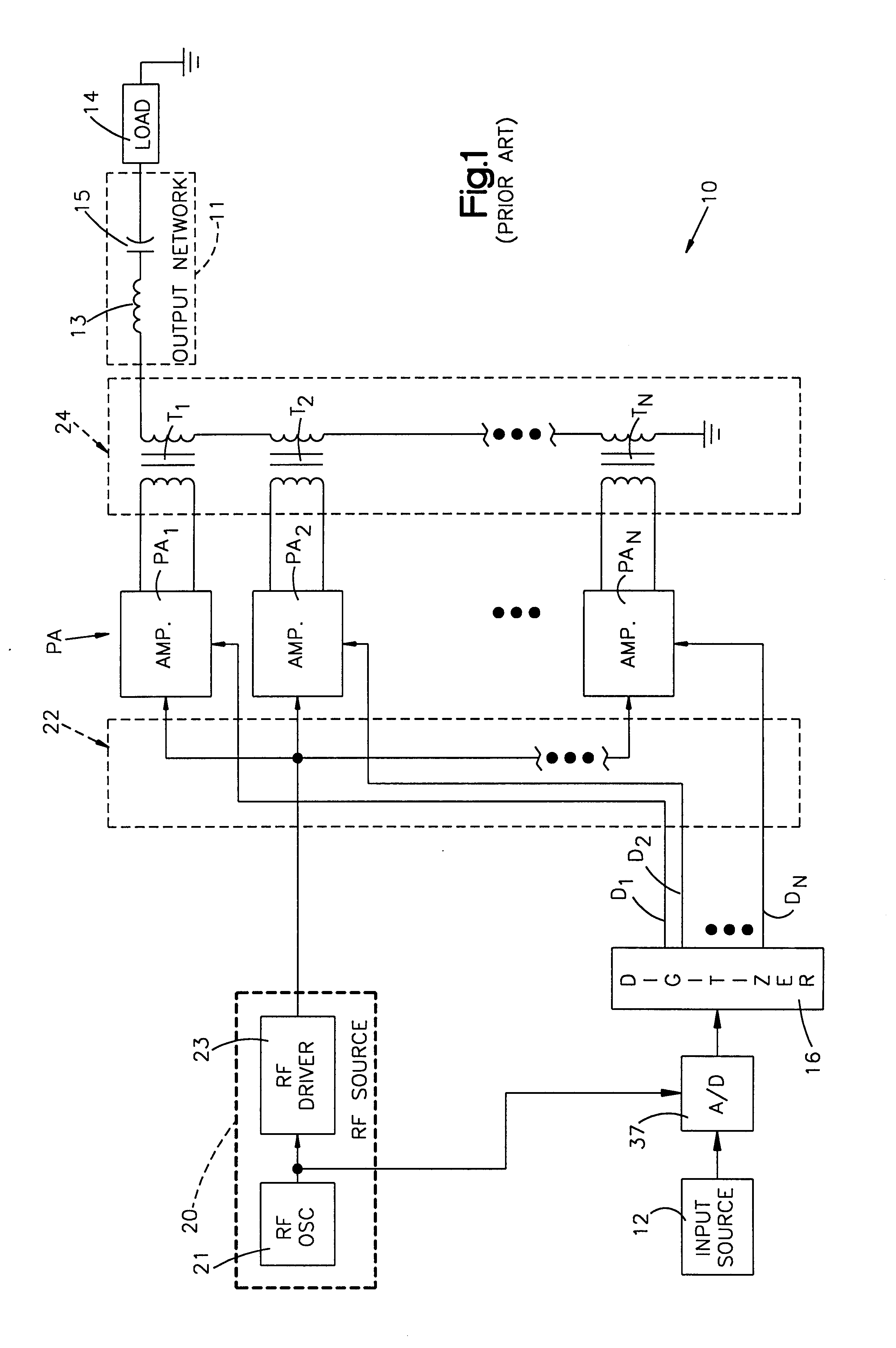
One application of the present invention is in conjunction with RF power amplifiers employed in an AM broadcast transmitter. An example of such a transmitter is presented in FIG. 1 and takes the form of a digital amplitude modulator such as that illustrated and described in the aforesaid U.S. Pat. No. 4,580,111, which is assigned to the same assignee as the present invention, the disclosure of which is herein incorporated by reference.

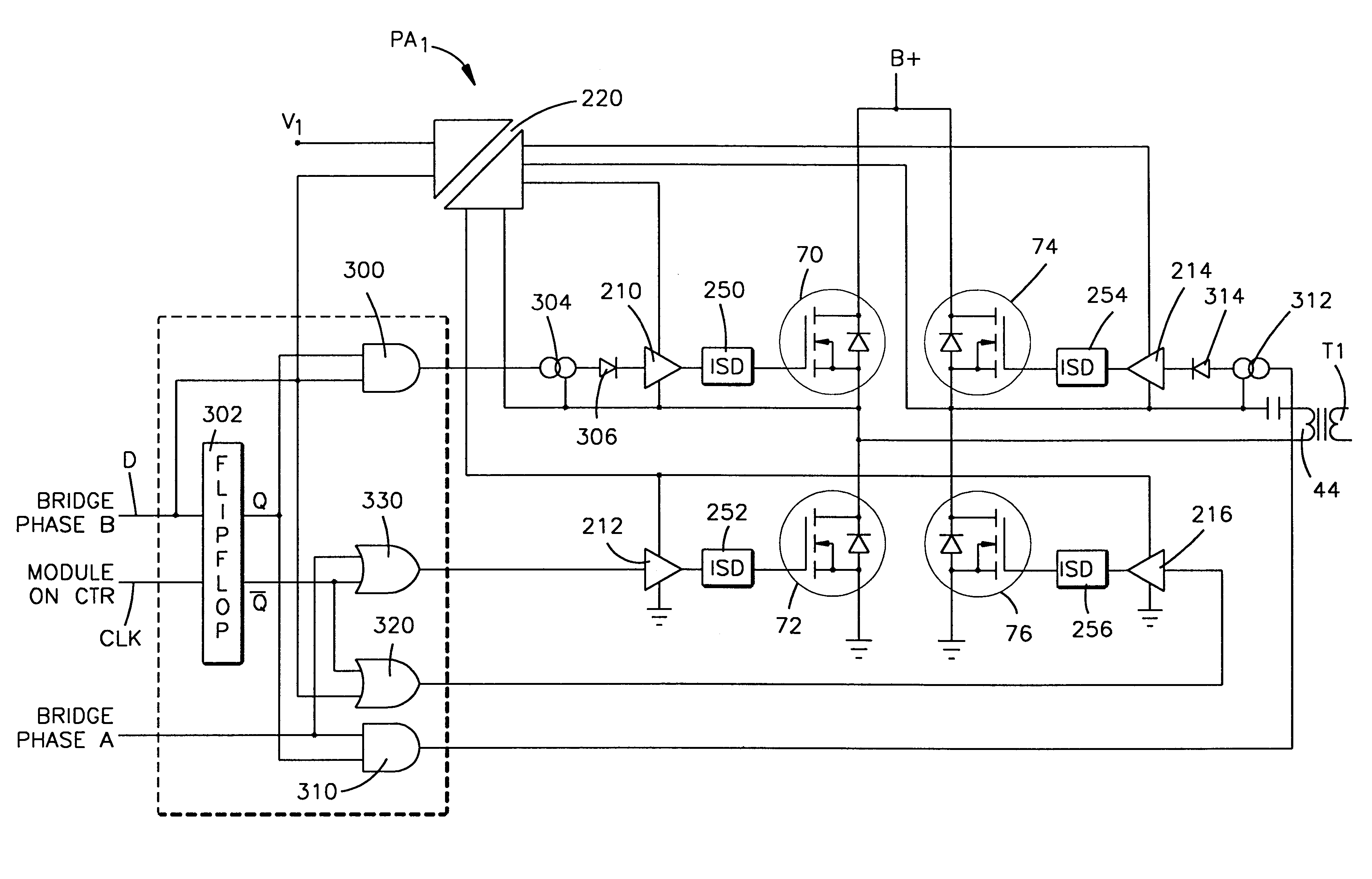
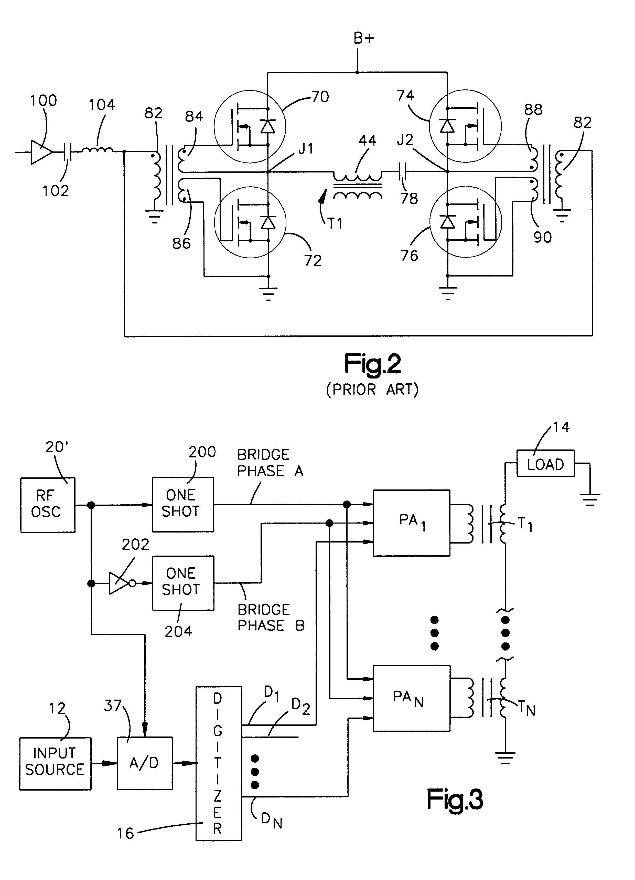
The discussion which follows is directed to an explanation of the operation of the circuitry shown in FIG. 1 followed by a detailed description of a power amplifier as illustrated in FIG. 2 herein as background for the discussion of the invention presented with respect to the embodiment illustrated herein in FIG. 3.

Referring now to FIG. 1, the amplitude modulator 10 is illustrated as receiving an input signal from input source 12 which may be the source of an audio signal. Modulator 10 generates an RF carrier signal which is amplitude modulated as a fu...


PUM


Abstract

A RF power amplifier system is presented herein including a RF source for providing a train of RF pulses exhibiting RF cycles of a fixed frequency and wherein each pulse is of a fixed amplitude and duration. A bridge circuit includes a first transistor switch for, when on, connecting the DC voltage source across a load for DC current flow therethrough in a first direction and a second transistor switch for, when on, connecting the DC voltage source across the load for DC current flow therethrough in a second direction. A switch driver serves, when enabled, to pass the RF pulses for driving the first and second transistor switches on and off at a frequency dependent upon that of the RF pulses and in such a manner that current from the DC voltage source alternately flows in the first and second directions through the load. A driver controller provides turn-on signals and selectively applies them to the switch driver for enabling the switch driver for passing the RF pulses to the transistor switches. The driver controller includes logic circuitry responsive to an amplifier turn-on control signal and the RF pulses for enabling the switch driver in such a manner that the first and second transistor switches are turned on and off in synchronism with the start of a RF cycle and the end of a RF cycle.

Description

1. Technical FieldThis invention relates to the art of AM radio broadcasting and, more particularly, to an RF power amplifier system of the type employed in AM radio broadcasting having synchronous RF drive.2. Description of the Prior ArtThe H. I. Swanson U.S. Pat. Nos. 4,580,111 and 4,949,050 disclose an amplitude modulator for use in AM radio broadcasting and wherein the modulator serves to generate an amplitude modulated signal by selectively turning on and off a plurality of RF amplifiers in a digital manner to produce amplitude modulation. Each of the RF amplifiers includes a plurality of switching transistors, each of which may take the form of a MOSFET transistor, connected together in a bridge circuit. This bridge circuit provides output signals to an output combiner. Each of the MOSFET transistors has a gate which is driven by properly phased RF frequency signals that allow the proper MOSFET transistors to be turned on at the correct times.The drive system for driving the R...

Claims


Application Information

Patent Timeline
IPC IPC(8): H03F3/20H03F3/217
CPCH03F3/2171H03F3/2178H03F3/2175H03F3/2173
Inventor LUU, KY THOAI
Owner GATESAIR
Why Eureka
Try Eureka