Fixed clock based arbitrary symbol rate timing recovery loop

Inactive Publication Date: 2001-09-25
LUCENT TECH INC
View PDF4 Cites 69 Cited by
  • Summary
  • Abstract
  • Description
  • Claims
  • Application Information

AI Technical Summary

Problems solved by technology

However, these conventional baud rate adjustments are limited to just a few hundreds or thousands of parts per million of the baud rate, and are not able to adjust through a wide range of baud rates wit

Method used


Image

  • Fixed clock based arbitrary symbol rate timing recovery loop
  • Fixed clock based arbitrary symbol rate timing recovery loop
  • Fixed clock based arbitrary symbol rate timing recovery loop

Examples


Embodiment Construction

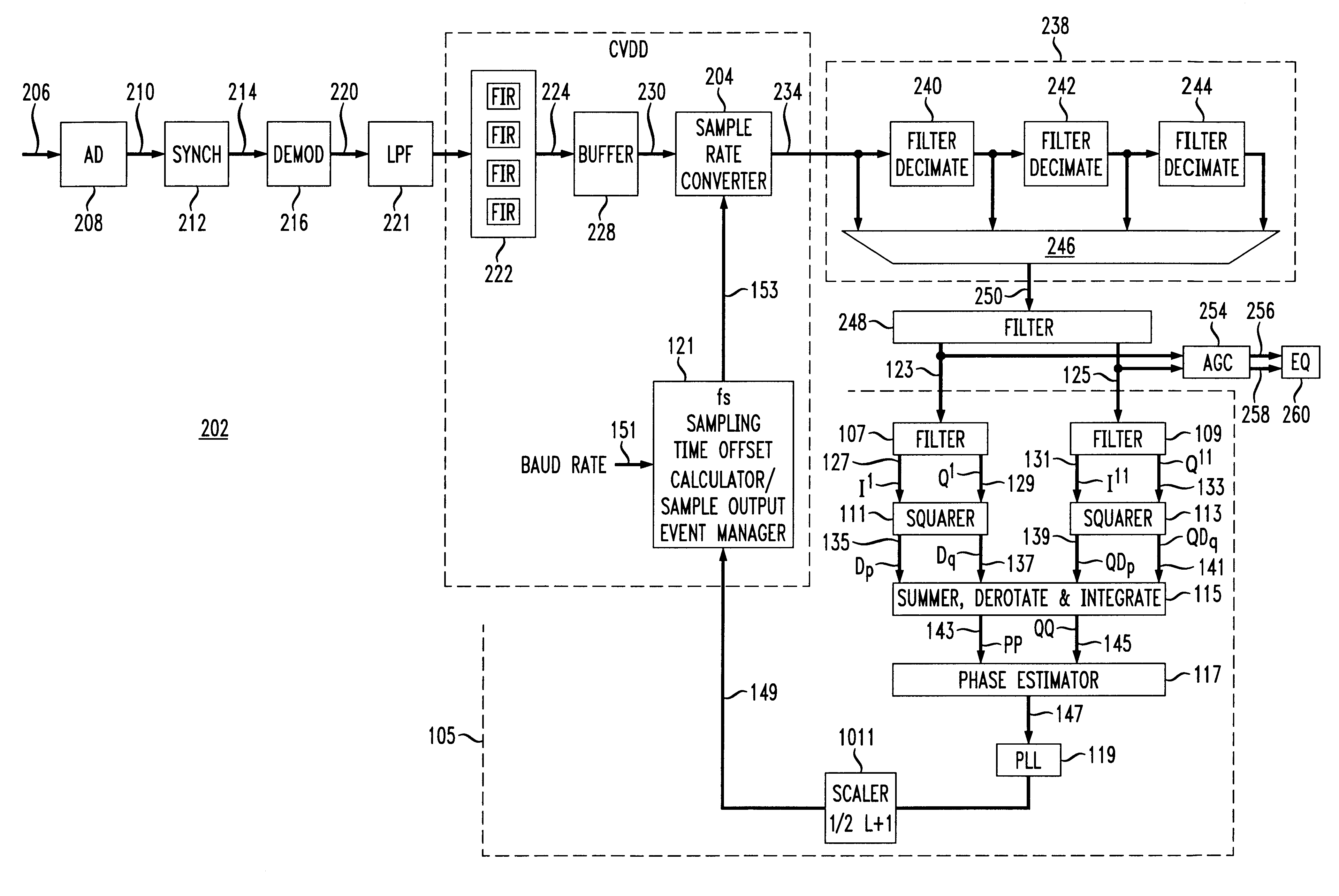
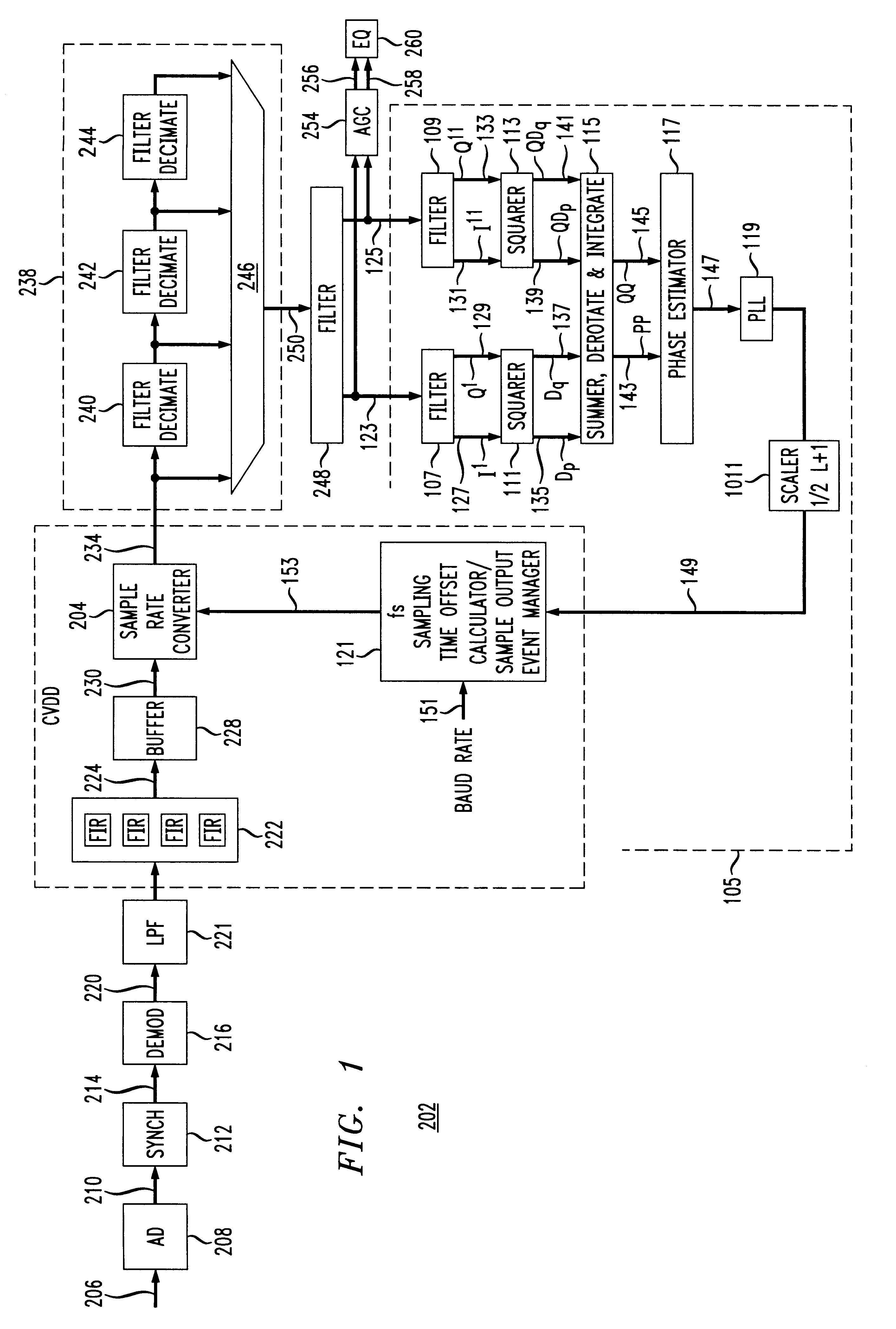
The disclosed embodiment of the present invention relates to a digital quadrature amplitude modulation (QAM) receiver that is capable of demodulation of a passband signal containing a digital signal having a baud rate which is anywhere in a wide range of possible baud rates. The input signal is sampled at a fixed rate fs, and an interpolator / decimator chain generates T / 2 samples at twice the received data signal baud rate for use with a fractionally spaced adaptive equalizer.

FIG. 1 is a simplified block diagram showing an embodiment of a demodulator 202 incorporating a timing recovery loop in a communication device, e.g., an integrated circuit based modem, in accordance with the principles of the present invention.

In particular, the demodulator 202 includes an A / D converter 208, a synchronizer 212, a demodulator circuit 216, a pair of low pass filters 221, a filter bank 222, two continuously variable interpolator / decimator circuits consisting of a buffer 228, sample rate converter 2...


PUM


Abstract

A QAM data signal timing recovery loop feedback element provides a fixed sampling time offset adjustment to two continuously variable digital rate interpolators/decimators to produce a quadrature output stream at a programmed rational rate multiple of the actual baud rate of the received data signal. The continuously variable digital rate interpolators/decimators are configured at startup so as to produce output streams at the same programmed rational rate multiple of the nominal baud rate of the anticipated received data signal, assuming the fs sample timing offset adjustment stream provided by the timing recovery feedback element to be identically 0. The "nominal" fixed sampling rate fs of the received analog input signal need not be rationally related to the nominal baud rate of the anticipated received data signal.

Description

This application is similar to the following co-pending U.S. patent applications, all of which are expressly incorporated herein by reference:U.S. patent application Ser. No.60 / 055,694, entitled "Variable Baudrate Demodulator", filed Jul. 15, 1997;U.S. Pat. No. 6,081,565 allowed on Jun. 27, 2000 entitled "Amplitude Based Course Automatic Gain Control Circuit", filed Jul. 15, 1997;U.S. patent application Ser. No. 09 / 019,402, entitled "Power Based Digital Automatic Gain Control Circuit", filed Jul. 15, 1997;U.S. Pat. No. 6,108,375 allowed on Aug. 22, 2000 entitled "Equalization Circuit for Unknown QAM Constellation Size", filed Jul. 15, 1997;U.S. patent application Ser. No. 60 / 052,572, entitled "Fixed Clock Based Arbitrary Symbol Rate Timing Recovery Loop", filed Jul. 15, 1997;U.S. Pat. No. 6,081,565 allowed on Jun. 27, 2000 entitled "Fixed Clock Based Arbitrary Symbol Rate Timing Recovery Loop", filed Jul. 15, 1997;U.S. patent application Ser. No. 60 / 052,572, entitled "Amplitude Base...

Claims


Application Information

Patent Timeline
IPC IPC(8): H04L7/027H04L7/00H04L7/02
CPCH04L7/027H04L7/0004H04L7/0029H04L7/0025H04L7/0278
Inventor FARROW, CECIL WILLIAMUDOVIC, DANIEL J.MARANDI, VAHIDMOBIN, MOHAMMAD SHAFIULMONDAL, KAYLANWONG, KAI-CHUEN
Owner LUCENT TECH INC
Why Eureka
Try Eureka