
Symbol based algorithm for hardware implementation of cyclic redundancy check

a hardware implementation and algorithm technology, applied in the field of circuit design, can solve problems such as the limitation that the stream must be bit-serial

Inactive Publication Date: 2001-09-25
HANGER SOLUTIONS LLC +1
View PDF4 Cites 30 Cited by
  • Summary
  • Abstract
  • Description
  • Claims
  • Application Information

AI Technical Summary

Problems solved by technology

While such a circuit is simple and can run at very high clock speeds, it suffers from the limitation that the stream must be bit-serial.

Method used


Image

  • Symbol based algorithm for hardware implementation of cyclic redundancy check
  • Symbol based algorithm for hardware implementation of cyclic redundancy check
  • Symbol based algorithm for hardware implementation of cyclic redundancy check

Examples


first embodiment

This first embodiment of the present invention provides adequate timing results in synthesis for values of n less than or equal to 16. In embodiments where n is greater than 16, this synthesis is not fully effective for at least two reasons:

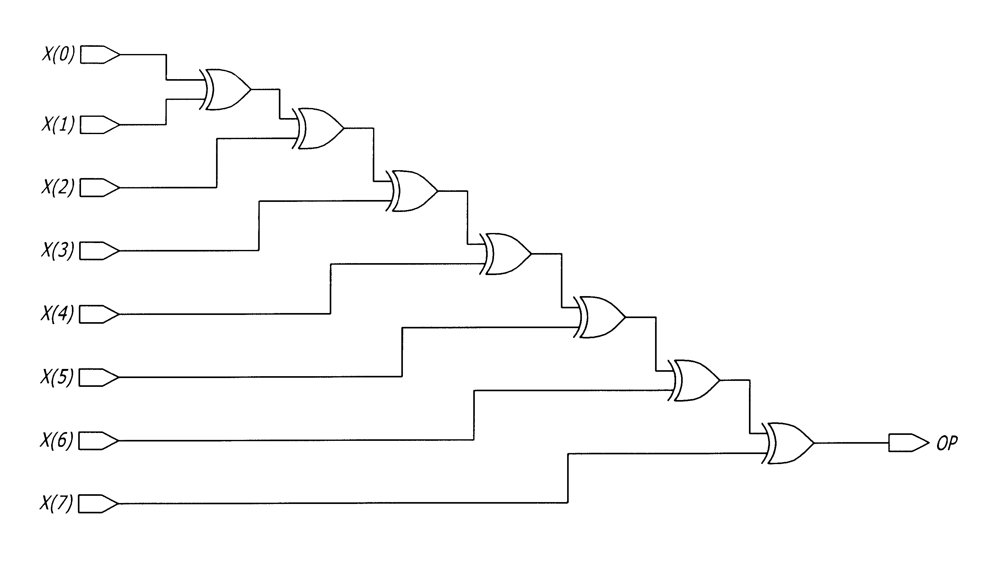
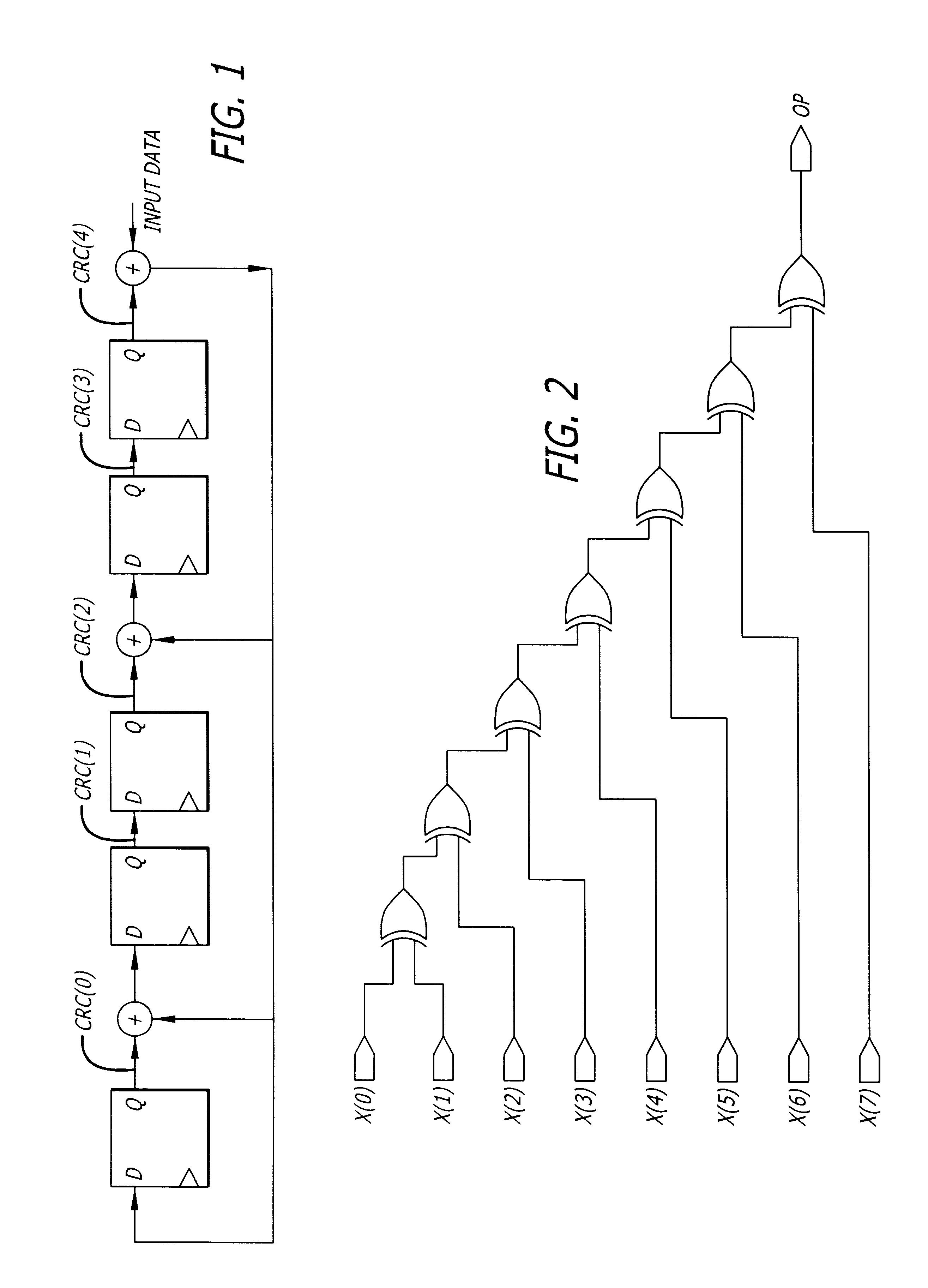
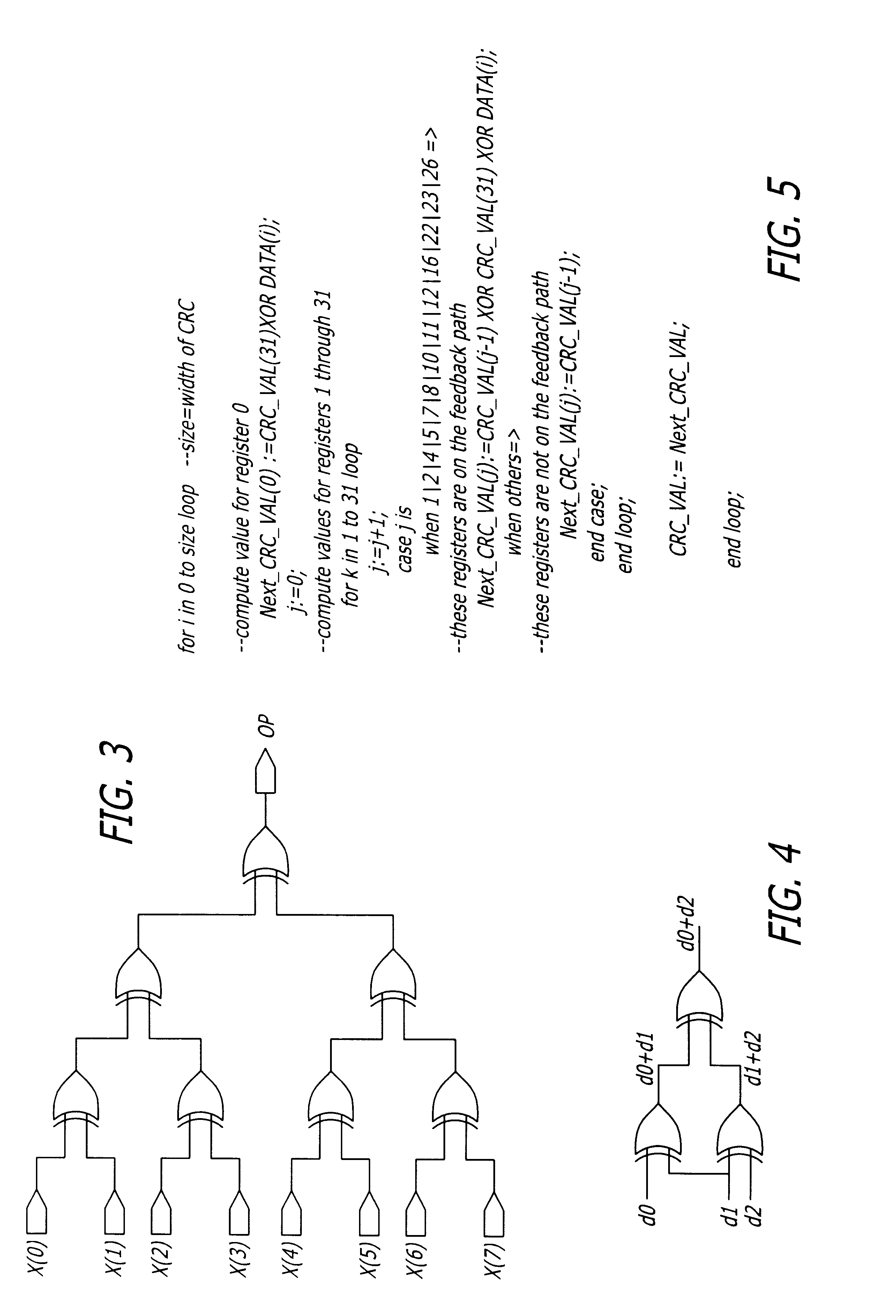
1. Due to the loop unrolling that takes place in RTL synthesis, the for-loop construct translates to a ripple implementation in gates and hence there could be up to n-levels of logic in the synthesis implementation for a loop of depth n (see FIG. 2). For example, FIG. 2 illustrates a ripple implementation of an XOR tree, with a maximum number of logic levels =7. This leads to a very slow timing path. By giving tight timing constraints for synthesis, the number of levels of logic can be reduced but our experiments show that for values of n greater than 16, the timing obtained through synthesis gets significantly worse than what could be achieved using a balanced tree implementation. (see FIG. 3). For instance, FIG. 3 illustrates a balanced tree im...


PUM


Abstract

A method and apparatus for generation of CRC generation / checker circuitry. A symbolic simulation-based algorithm to derive boolean equations for a parameterizable data-width CRC generator / checker is described. The equations generated are used to implement a data-flow representation of the CRC circuit in VHDL. The VHDL description is then synthesized into gates.

Description

1. Field of the InventionThe present invention relates to the field circuit design and, more specifically to design of circuits for calculating cyclic redundancy check (CRC) codes.2. Description of the Related ArtCyclic redundancy check (CRC) codes have many uses. In computer networking, for example, a CRC code is a very powerful tool and easily implemented technique to obtain data reliability in networking. The CRC technique is used to verify the integrity of blocks of data called Frames. Using this technique, the transmitter appends an extra n bit sequence to every frame called Frame Check Sequence (FCS). FCS holds redundant information about the frame that helps the receiver detect errors in the frame. CRC is one of the most commonly used techniques for error detection in data communications.One known hardware implementation of a bit-wide CRC generator is a simple linear feedback shift register (see FIG. 1.). For example, FIG. 1 illustrates a bit wide CRC generator for the polyno...

Claims


Application Information

Patent Timeline
IPC IPC(8): H03M13/09H03M13/00H03M13/15
CPCH03M13/091H03M13/6575H03M13/15
Inventor NAIR, RAJESH G.RYAN, GERRYFARZANEH, FARIVAR
Owner HANGER SOLUTIONS LLC
Learn More