Switch having an insulating support

a technology of insulating support and switch, which is applied in the direction of relays, contacts, thermal switch details, etc., can solve the problems of inability to operate, further disadvantage, and difficulty in design terms, and achieves the effect of reducing the number of switches

Inactive Publication Date: 2001-10-09
HOFSASS MARCEL
View PDF20 Cites 38 Cited by
  • Summary
  • Abstract
  • Description
  • Claims
  • Application Information

AI Technical Summary

Benefits of technology

The reason is that because of the mechanical series circuit, i.e. the fact that the spring force of the spring element coacts with that of the switching member, the creep phase of the switching member can be compensated for. When the geometry of the switching member changes during the creep phase, this is immediately compensated for by the spring element. It is therefore now possible for the first time, even in the case of a switch having a switching member through which current flows (which can be a bimetallic or trimetallic element), to allow a large creep phase for the switching member, since the spring element can compensate for the "undesired" changes in shape during the creep phase. This means, however, that a more easily manufactured and therefore more economical switching member, which moreover has a longer service life, can be used, since dimpling can be largely dispensed with and a greater hysteresis thus becomes permissible, so that the creep phase can be maximally utilized.
The advantage of this feature is that overall height is greatly reduced as compared to the generic switch, and a lesser longitudinal extension is also achieved because of the "folded-back" free end of the switching member.

Problems solved by technology

The principal disadvantage of this design is that two bimetallic elements, whose temperature characteristics must exactly match with one another, are required; this is difficult and cost-intensive to implement in design terms.
In order to compensate for production tolerances, the known switch is moreover mechanically adjusted after assembly, which constitutes a further disadvantage.
This is no longer possible during service, however, the overall result being that long-term stability and therefore operating reliability leave much to be desired.
A further disadvantage with this design is the large overall height necessitated by the U-shaped bimetallic element.
Lastly, a further disadvantage with this switch is that it automatically closes again after cooling off, i.e. has no self-hold function that prevents re-closing and thus reactivation of the electrical device protected by the switch.
A further disadvantage that is associated with the known switches having a self-hold function consists in the design outlay, which results in cost-intensive switches that are difficult to assemble.
A further disadvantage associated with the switch mentioned at the outset is the fact that the threshold value of the current that results in opening of the switch is determined by the ohmic resistance of the bimetallic element, so that it is difficult to implement different switching current values.
It is also the case with the known switches having a series resistor that the design outlay is disadvantageous and assembly of the switches is cost-intensive and time-consuming.
One disadvantage of this switch is the fact that during the transition from the closed to the open position, the bimetallic spring tongue, like all bimetallic elements, passes through a "creep" phase in which the bimetallic element deforms in creeping fashion in response to an increase or decrease in temperature, but without yet snapping over from its, for example, convex low-temperature position into its concave high-temperature position.
This creep phase occurs whenever the temperature of a bimetallic element approaches the kickover temperature either from above or from below, and results in appreciable conformational changes.
In addition, the creep behavior of a bimetallic element can also change, in particular, as a result of aging or long-term operation.
During the opening movement, creep can result in a weakening of the pressure of the contact against the countercontact, thus causing undefined switching states.
During the closing movement, the contact can gradually approach the countercontact during the creep phase, which can lead to the risk of arcing.
These dimples or other mechanical impressions provided for suppressing the creep phase onto the bimetallic element are complex and expensive features which moreover greatly reduce the service life of these bimetallic elements.
A further disadvantage of the requisite dimple is that not only different material compositions and thicknesses, but also different dimples, must be used for various power classes and response temperatures.
Note also that this assembly operation is greatly simplified as compared, for example, to the assembly of a switch as defined in DE 21 21 802 C, since the operation therein, to be performed only manually, of setting in place the bimetallic snap disk and the spring disk slipped over it is highly wage-intensive and moreover often results in wastage.

Method used


Image

  • Switch having an insulating support
  • Switch having an insulating support
  • Switch having an insulating support

Examples


Embodiment Construction

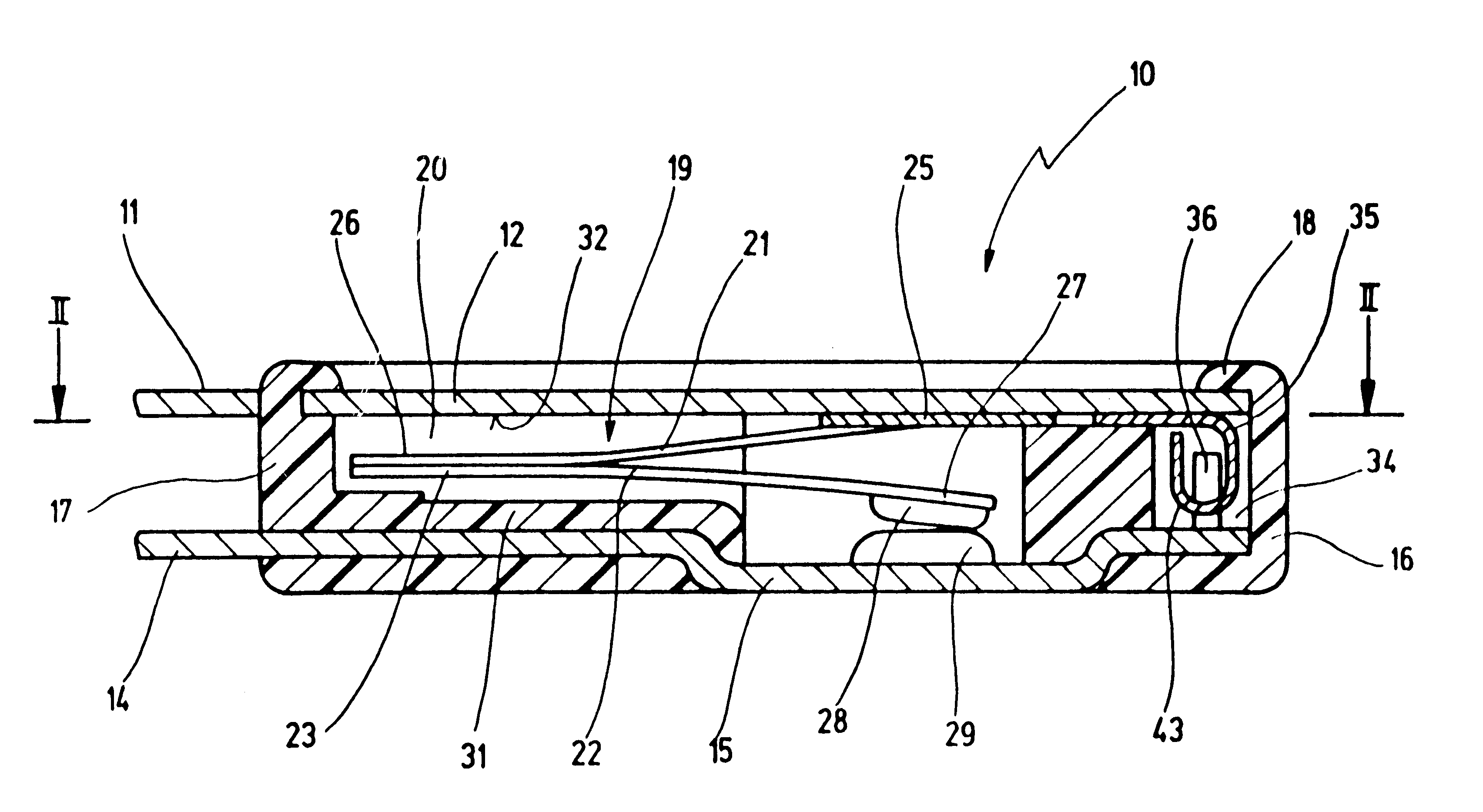
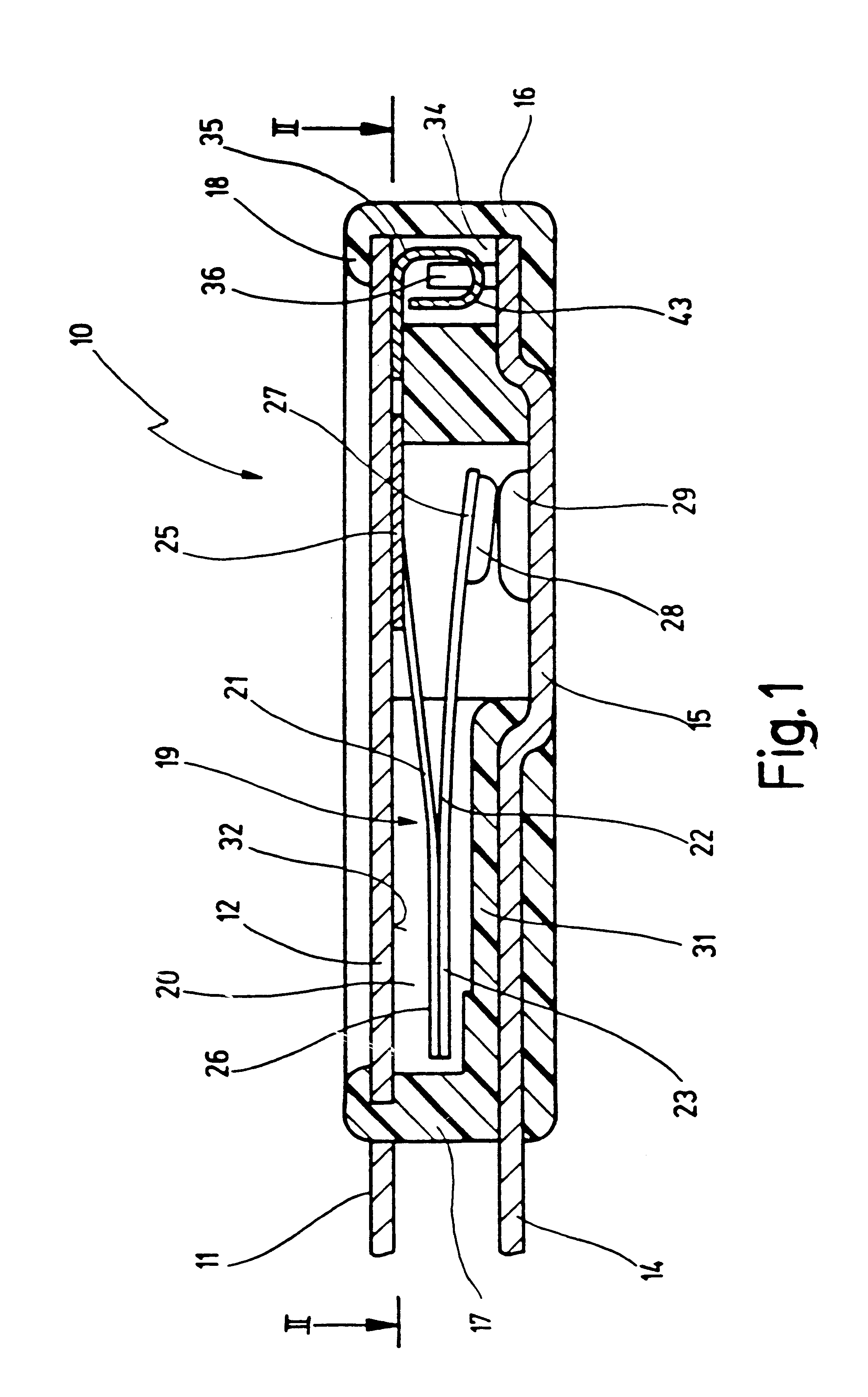
In FIG. 1, reference numeral 10 generally designates a new switch, which is shown in schematic longitudinal section.

The new switch 10 has a first external terminal 11 that is joined integrally to a flat or planar cover electrode 12. Also provided is a second external terminal 14 that is configured integrally with a bottom electrode 15. Cover electrode 12 and bottom electrode 15 are retained on an insulating support 16 that holds cover electrode 12 and bottom electrode 15 spaced apart parallel to one another.

While insulating support 16 can theoretically be open laterally, FIG. 1 shows an embodiment in which insulating support 16 comprises a cup-shaped lower housing part 17 that is configured around bottom electrode 15, by injection embedding or encapsulation, in such a way that bottom electrode 15 is an integral constituent of lower housing part 17. Lower housing part 17 is closed off by cover electrode 12 and is held in lossproof fashion by a hot-welded rim, indicated at 18, of insu...


PUM


Abstract

A switch 10 has an insulating support 16 on which a first and a second external terminal 11, 14 are arranged, and a temperature-dependent switching mechanism 19 that, as a function of its temperature, makes between the first and the second external terminal 11, 14 an electrically conductive connection for an electrical current to be conducted through the switch 10, and having a switching member 22 that changes its geometric shape in temperature-dependent fashion between a closed position and an open position and in its closed position carries the current. An actuating member is connected electrically and mechanically in series with the switching member 22. The first external terminal 11 is connected to a planar cover electrode 12, to which the actuating member is fastened with its first end 25. The cover electrode 12 has on its inner side 32 a flat self-hold resistor that is electrically connected between the cover electrode 12 and the second external terminal 14.

Description

1. Field of the InventionThe present invention concerns a switch having an insulating support on which a first and a second external terminal are arranged, and having a temperature-dependent switching mechanism that, as a function of its temperature, makes between the first and the second external terminal an electrically conductive connection for an electrical current to be conveyed through the switch, and comprises a switching member that changes its geometric shape in temperature-dependent fashion between a closed position and an open position, in its closed position the switching member carrying the current, an actuating member being provided that is connected electrically and mechanically in series with the switching member.2. Related Prior ArtA switch of this kind is known from U.S. Pat. No. 4,636,766.The known switch comprises, as the switching member, a U-shaped bimetallic element having two legs of different lengths. Attached to the long leg is a movable contact element tha...

Claims


Application Information

Patent Timeline
Patent Type & Authority Patents(United States)
IPC IPC(8): H01H1/00H01H37/00H01H1/50H01H37/54H01H71/16H01H71/12
CPCH01H1/504H01H37/5418H01H37/5427H01H71/16H01H2037/5445H01H2037/5463
Inventor HOFSASS, MARCEL
Owner HOFSASS MARCEL
Why Eureka
Try Eureka