Vibration measurement method and apparatus

a measurement method and vibration technology, applied in the field of vibration measurement methods and apparatuses, can solve the problems of difficult to observe a speed change during the vibration plane displacement, difficult to calculate vibration, and difficult to output a result at real tim

Inactive Publication Date: 2001-10-16
SUZUKI MOTOR CORP
View PDF9 Cites 46 Cited by
  • Summary
  • Abstract
  • Description
  • Claims
  • Application Information

AI Technical Summary

Problems solved by technology

Furthermore, in the conventional example, there is a problem that when the vibrating object displaces by a very small displacement, it is impossible to calculate vibration by replacing the Doppler frequency wi

Method used


Image

  • Vibration measurement method and apparatus
  • Vibration measurement method and apparatus
  • Vibration measurement method and apparatus

Examples


Embodiment Construction

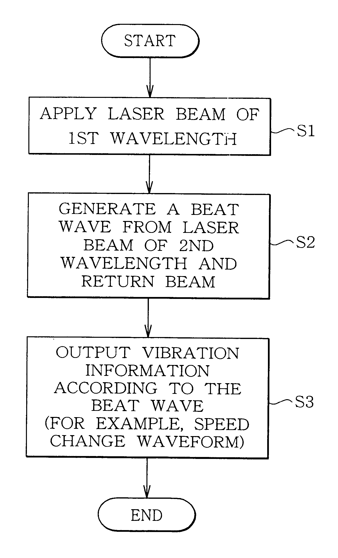
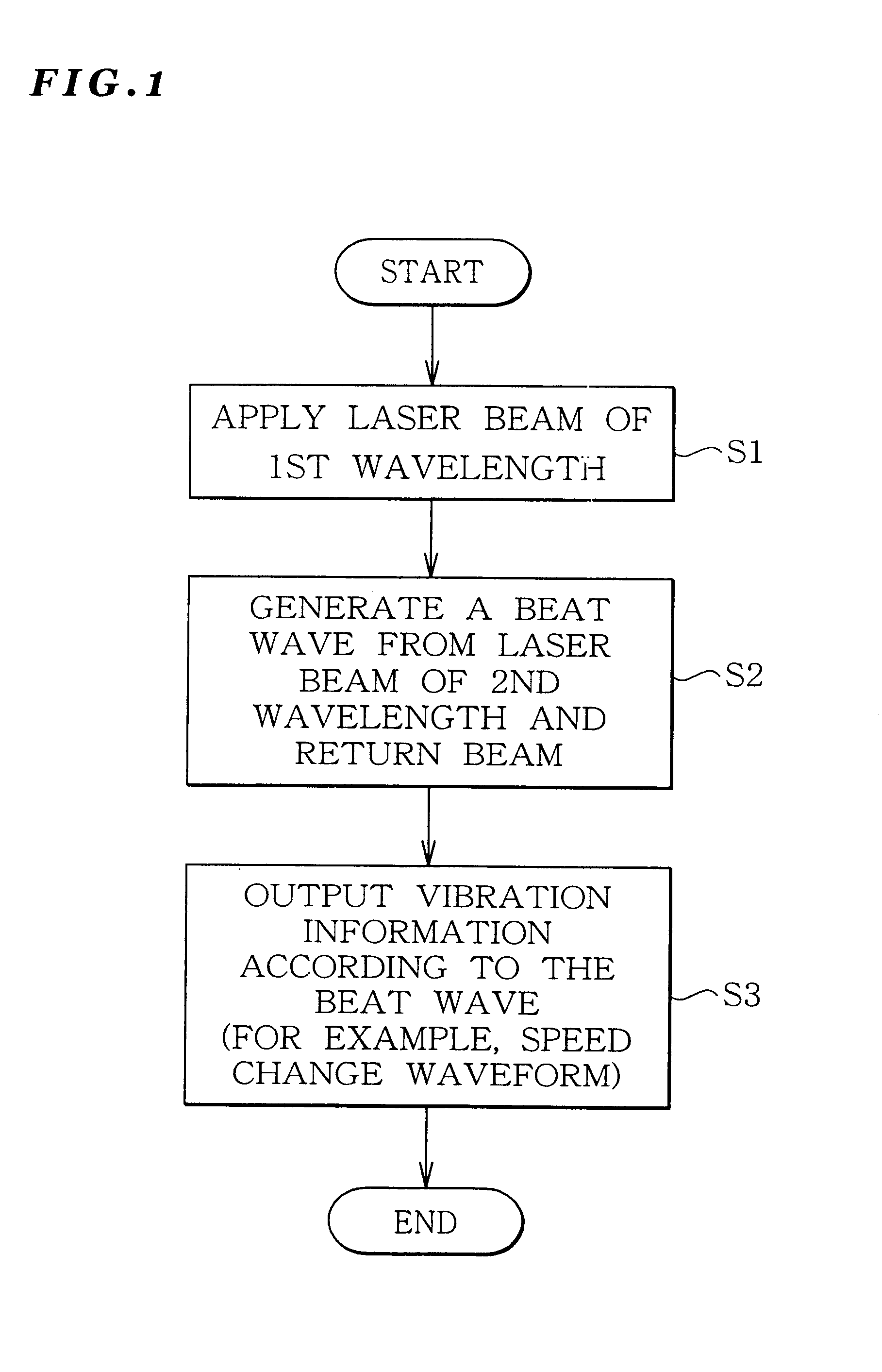
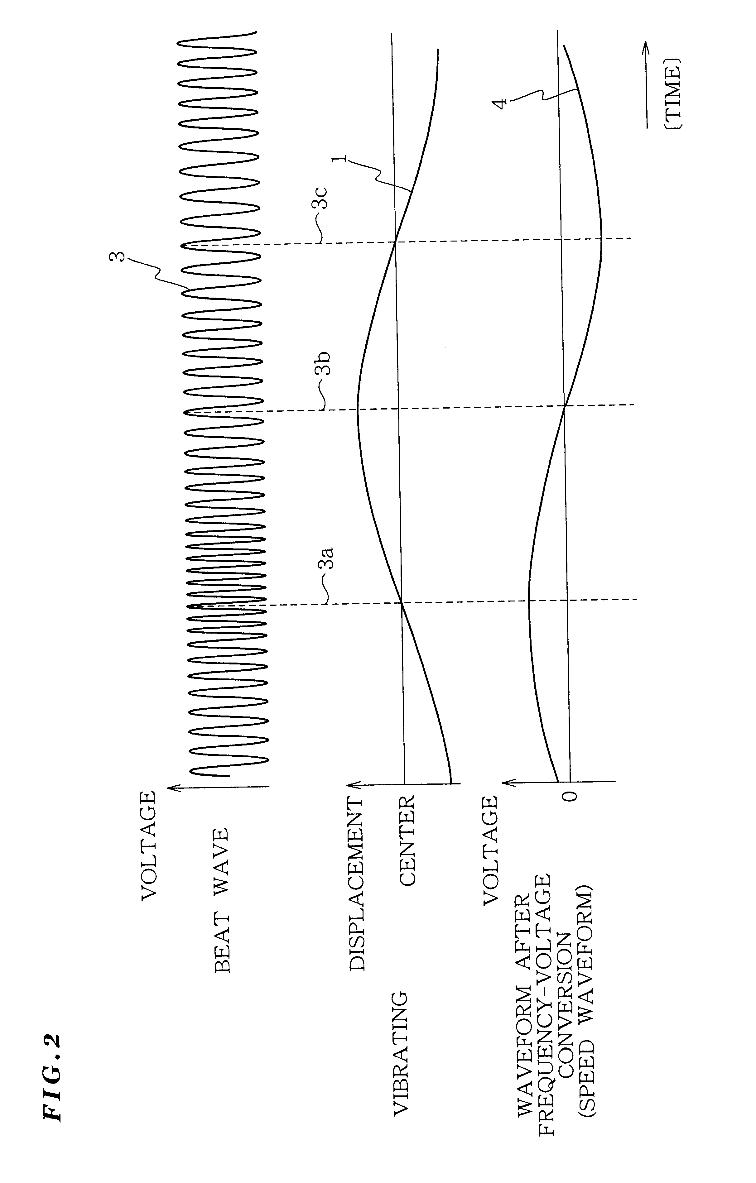
Explanation will be given on an example of the embodiment. As shown in FIG. 11, the vibration measurement apparatus of this example includes; a laser resonator 14 for applying a laser beam to an object to be measured and receiving a return beam reflected by the object to be measured; a laser drive unit 18 for driving the laser resonator 14 with a modulated drive current; and a beat wave output unit 30 for outputting a beat wave generated by self-mixing in the laser resonator 14. Moreover, the laser drive unit 18 is set in such a manner that a wavelength difference between the a first wavelength when emitting a laser beam and a second wavelength when receiving a return beam, is in a relationship that the frequency (Fa) corresponding to the wavelength difference is equal to or above an inverse (2 / Ta) of the half (Ta / 2) of the vibration cycle (Ta) of the object to be measured.

This will be detailed below.

In this example, the vibration measurement apparatus includes a photo detection ele...


PUM


Abstract

The present invention provides a vibration measurement method and apparatus capable of accurately measuring displacement even if the displacement is very small. The vibration measurement method according to the present invention comprises: a laser beam application step (step S1) for applying a laser beam of a first wavelength to an object to be measured; a beat wave generation step (step S2) for mixing a laser beam of a second wavelength which is different from the first wavelength and the return beam reflected from the object to be measured; and a vibration information output step (step S3) for outputting the beat wave thus generated as a vibration information of the object to be measured.

Description

1. Field of the InventionThe present invention relates to a vibration measurement method and apparatus and in particular, to a vibration measurement method and apparatus capable of detecting a very small displacement, speed, and periodicity.This vibration measurement method and apparatus can be applied to an experiment analysis such as an automobile production technology. More specifically, engine vibration analysis, body transmission and vibration analysis, analysis of noise in the cabin, and muffler vibration analysis. The present invention can also be applied to various other fields. Since the present invention can accurately measure a very small vibration with a non-contact state, it can be applied to an instrument damage such as a drill. Furthermore, the present invention can be applied to vibration of a plant using a motor, leak of a water pipe and a gas pipe. Furthermore, sweetness of a large size fruit such as watermelon can be checked according to the vibration caused by kn...

Claims


Application Information

Patent Timeline
IPC IPC(8): G01B9/02G01S17/00G01S17/58G01H9/00
CPCG01S17/58G01B9/02045G01B9/02003G01B9/02069G01B9/02083
Inventor MARUYAMA, TETSUROOHNO, AKIYOSHI
Owner SUZUKI MOTOR CORP
Why Eureka
Try Eureka