
Steam valve

a technology of steam valve and steam, which is applied in the direction of valve operating means/releasing devices, mechanical equipment, transportation and packaging, etc., can solve the problems of substantial waste of money and natural resources, substantial waste of energy, and substantial waste of condensa

Inactive Publication Date: 2001-10-16
3M INNOVATIVE PROPERTIES CO
View PDF32 Cites 25 Cited by
  • Summary
  • Abstract
  • Description
  • Claims
  • Application Information

AI Technical Summary

Benefits of technology

Steam valves according to the present invention have an increased service life, typically a significantly increased service life, over conventional comparable steam valves. In other words, a steam valve according to the present invention, having the metal nitride and / or carbide coating, typically has a longer service life than the same steam valve without the metal nitride or carbide coating. The metal nitride and / or carbide tends to significantly reduce the deterioration (e.g., corrosion) of the metal steam valve surface such coating is on.

Problems solved by technology

The condensate interferes with the efficient transport and heat transfer of the steam, particularly through a pipe.
Ideally, the steam valve allows condensate to flow through the passageway and to be discharged, while not allowing steam to pass through the passageway.
Poor or defective operation of a steam valve(s) can lead to a substantial waste of energy, which in turn can lead to a substantial waste of money and natural resources.
), then approximately $525,000 of steam is lost (and wasted) from the system per year.
The general mechanical nature of steam valves makes them prone to wear and deterioration.
A significant factor contributing to the shortened service life of a valve is typically corrosion.
Another factor affecting service life of a valve is mechanical stress, which is due, for example, to repeated contacting of the valve plug and valve seat during the opening and closing of the valve.
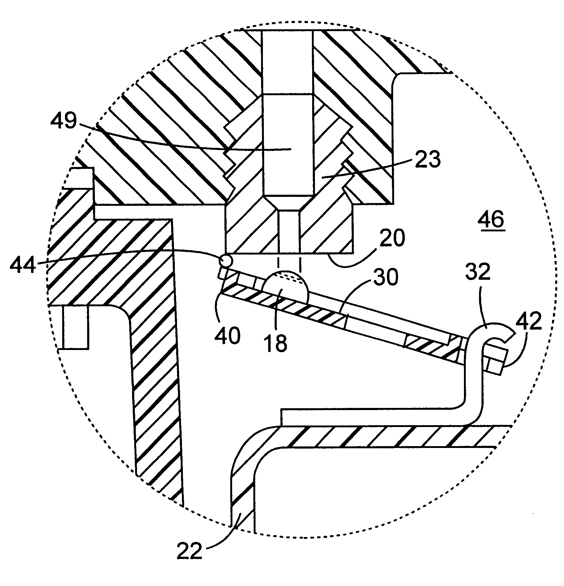
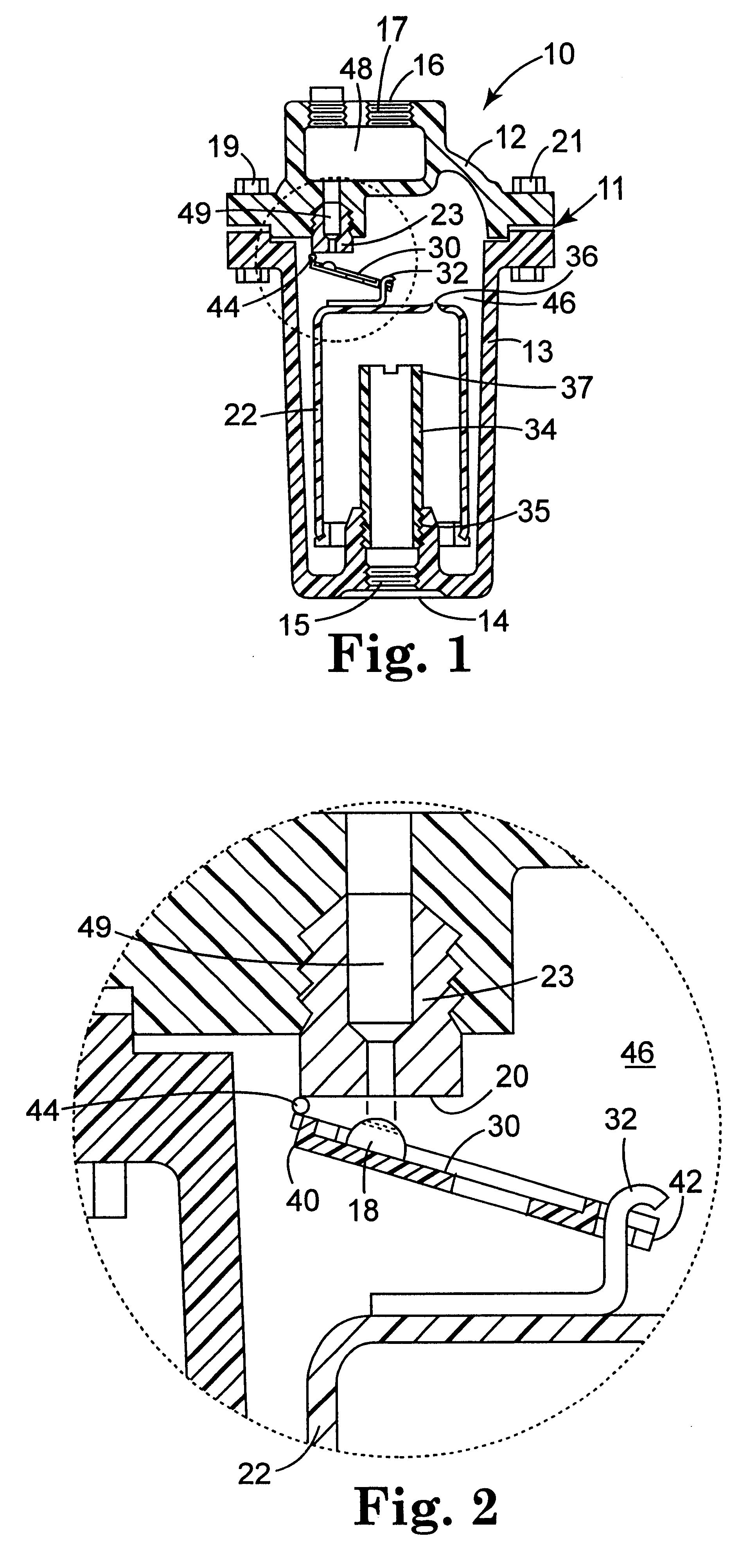
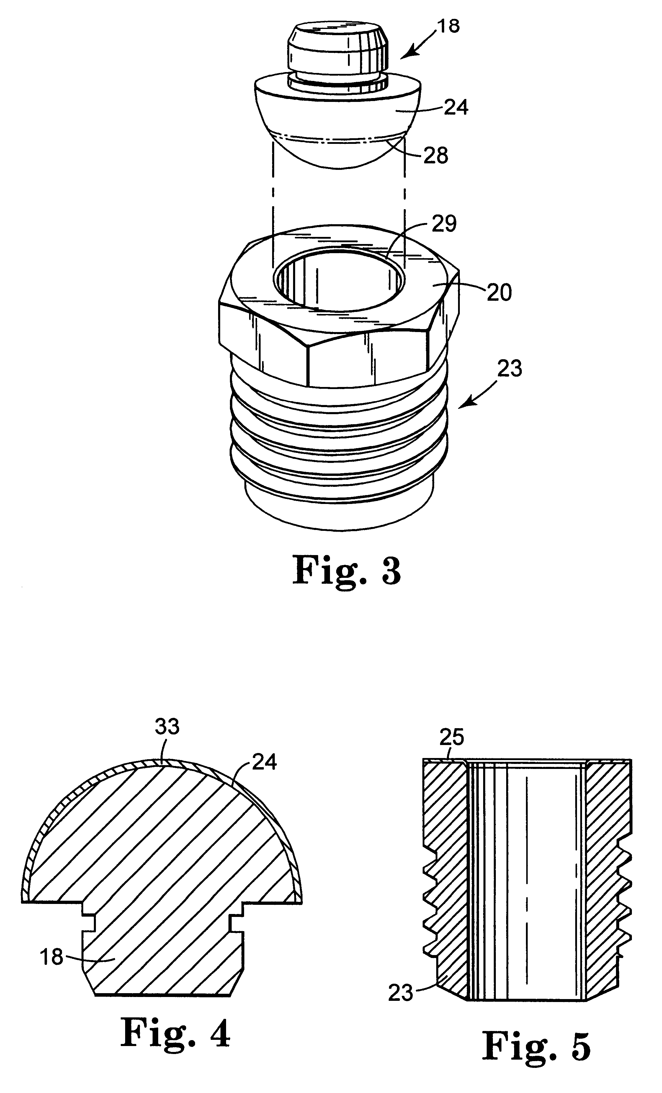
Corrosion (e.g., resulting in pitting) of valve plug and valve seat surfaces which contact each other when the valve is closed are particularly troublesome.
Such corrosion leads to an inability of the valve plug to properly couple with the valve seat and seal against or prevent passage of steam through the valve.
Although hardening may reduce valve seat wear, the hardened valve seat may be more brittle, and hence more prone to fracture from repeated contact between the valve seat and valve plug.

Method used


Image

  • Steam valve
  • Steam valve
  • Steam valve

Examples


example 1

The valve plug and valve seat were removed from a steam valve repair kit (referred to as "B1671-1, PCA 1 / 2 Less Bucket, 213-813A883-15 psi", and obtained from Armstrong International, Inc., Three Rivers, Mich.). The valve plug and valve seat were made of stainless steel, and had a Knoop hardness of about 481 and 721, respectively (measured using Knoop hardness tester available under the trade designation "BUELER MICROMET IV" from Bueler Instruments; 500 gram load, 15 second dwell).

A TiN coating was applied to the face of the valve seat (which included the valve seat mating surface), and to a major surface of the valve plug (which included the valve plug mating surface) using a physical vapor deposition technique (more specifically, Multi-Arc, Inc. of West St. Paul, Minn. applied a TiN coating using their physical vapor deposition technique marketed under the trade designation "ION BOND"). Multi-Arc's trade literature provides the following typical property values for TiN coatings ap...

example 2

A valve plug and valve seat element were removed from a steam valve repair kit (referred to as "B1669-2 PCA 3 / 16 Less Bucket 800-880A--20 psi, 981--50 psi" obtained from Armstrong International, Inc.). The valve plug and valve seat were made of stainless steel.

A TiN coating was applied to the major surface of the valve plug (which included the valve plug mating surface) using the technique described in Example 1. A very thin overspray of TiN was also applied by Multi-Arc, Inc. to the major surface of the valve plug (which included the valve plug mating surface).

The steam valve repair kit was reassembled and installed into an inverted bucket steam valve (available as Model #880 from Armstrong International, Inc.) operating as part of one of the 3M Company's (located in Maplewood, Minn.) facilities steam distribution systems. The inverted bucket steam valve operated at a temperature of about 163.degree. C. (325.degree. F.), a pressure of about 105 kPa (15 psig), and had a valve cycle ...


PUM

PropertyMeasurementUnit
thicknessaaaaaaaaaa
thicknessaaaaaaaaaa
pressureaaaaaaaaaa

Abstract

Steam valve wherein at least one of the valve plug mating surface or valve seat mating surface has a metal nitride and / or carbide coating thereon. Preferably, the metal nitride and / or carbide coating is on both mating surfaces.

Description

The present invention relates to steam valves having a valve plug or valve seat which have coated thereon a metal nitride and / or metal carbide coating.DESCRIPTION OF RELATED ARTSteam is commonly transported under pressure (e.g., 35 kPa to 4200 kPa (5 psi to 600 psi)) through a pipe or tunnel system as a way to move energy from one location to another. Such energy is used, for example, for heating, drying, cooking, manufacturing processes, curing, or driving a turbine. In transporting the steam, at least some condensate or liquid water is usually formed. The condensate interferes with the efficient transport and heat transfer of the steam, particularly through a pipe. Steam valves are therefore commonly used to remove condensate from steam transport systems. Generally, such valves allow condensate to be released from the steam system, while preventing, or at least minimizing, the loss of steam during condensate release.Steam valves typically are comprised of a conduit comprising a fi...

Claims


Application Information

Patent Timeline
Patent Type & Authority Patents(United States)
IPC IPC(8): F16K25/00F16K31/26F16K31/18F16T1/38F16T1/00
CPCF16K25/005F16K31/26F16T1/38Y10T137/304Y10T137/3068Y10T137/3046
Inventor WEAVER, BILLY LEEWOIAK, MICHAEL R.BOOTH, TIMOTHY N.
Owner 3M INNOVATIVE PROPERTIES CO
Learn More