Transmitter adjusting output power

a technology of output power and transmitter, applied in the direction of power management, wireless communication, gain control, etc., can solve the problems of increasing the power source battery of the mobile telephone, affecting the communication, and affecting the service life of the mobile telephon

Inactive Publication Date: 2001-10-16
ALPS ALPINE CO LTD
View PDF6 Cites 36 Cited by
  • Summary
  • Abstract
  • Description
  • Claims
  • Application Information

AI Technical Summary

Problems solved by technology

If the field intensity of the receive wave reaching the calling party's mobile telephone is weak, the link with the other party may be so affected by noise and the like that satisfactory communication is difficult or sometimes even impossible.
This is not desirable because the exhaustion of the power source battery of the mobile telephone would correspondingly increase.
Since a cordless mobile telephone uses a battery as its power source, when the mobile telephone is used beyond a certain length of time, its battery becomes exhausted and the mobile telephone can no longer be used.
In a mobile telephone having a transmitter using the first gain adjusting means or one having a transmitter using second gain adjusting means, their respective variable gain amplifying stages 32 and 41 are so adjusted as to achieve the required transmit signal level according to the relative level of the receive signal, the service life of the power source battery is extended by reducing the current consumption of the variable gain amplifying stage 32 or 41 when the required transmit signal level is adjusted to be relatively low, but the elongation of the battery's life is not sufficient and, by no means satisfactory.

Method used


Image

  • Transmitter adjusting output power
  • Transmitter adjusting output power
  • Transmitter adjusting output power

Examples


Embodiment Construction

A preferred embodiment of the present invention will be described below with reference to the accompanying drawings.

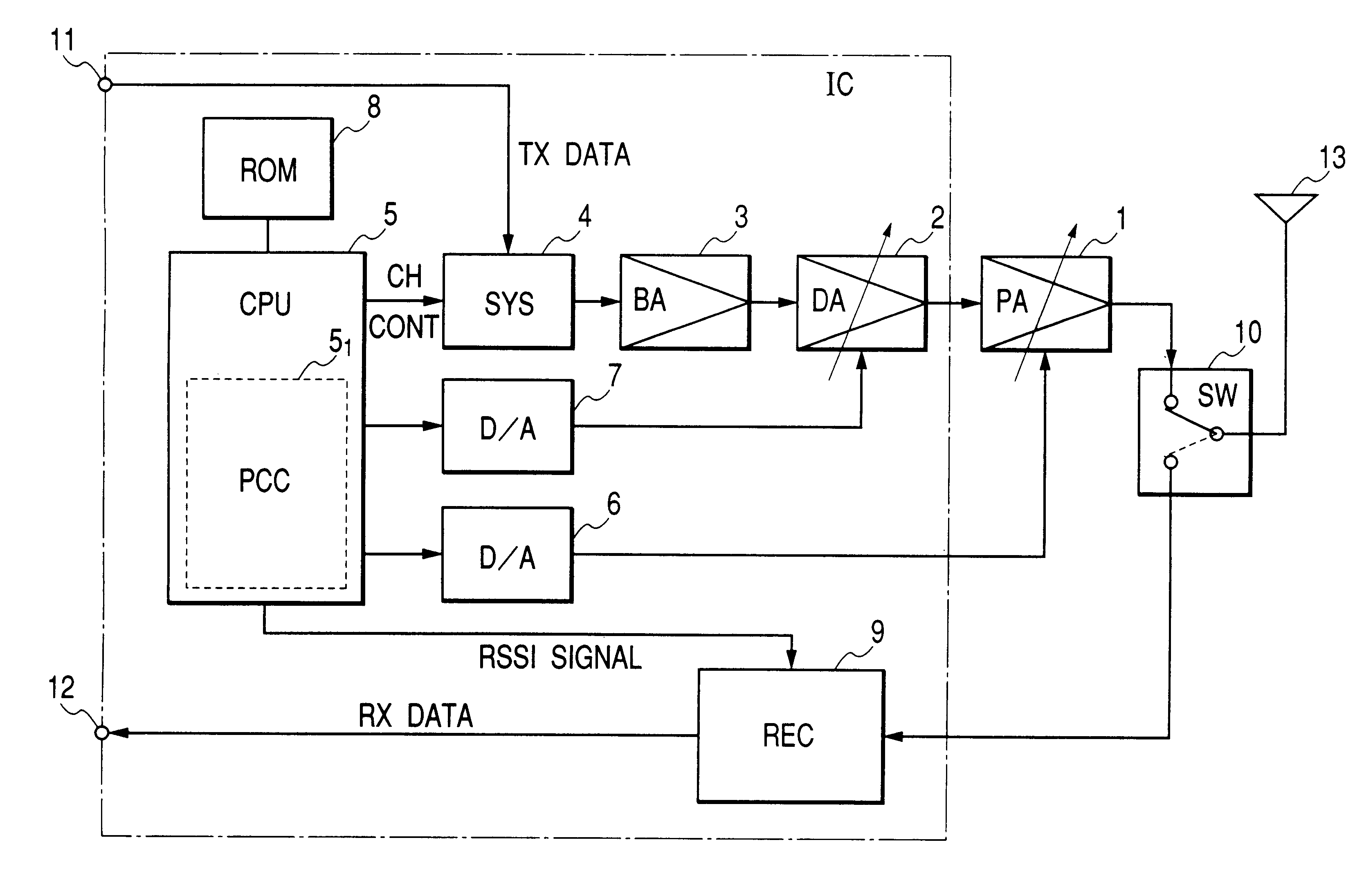
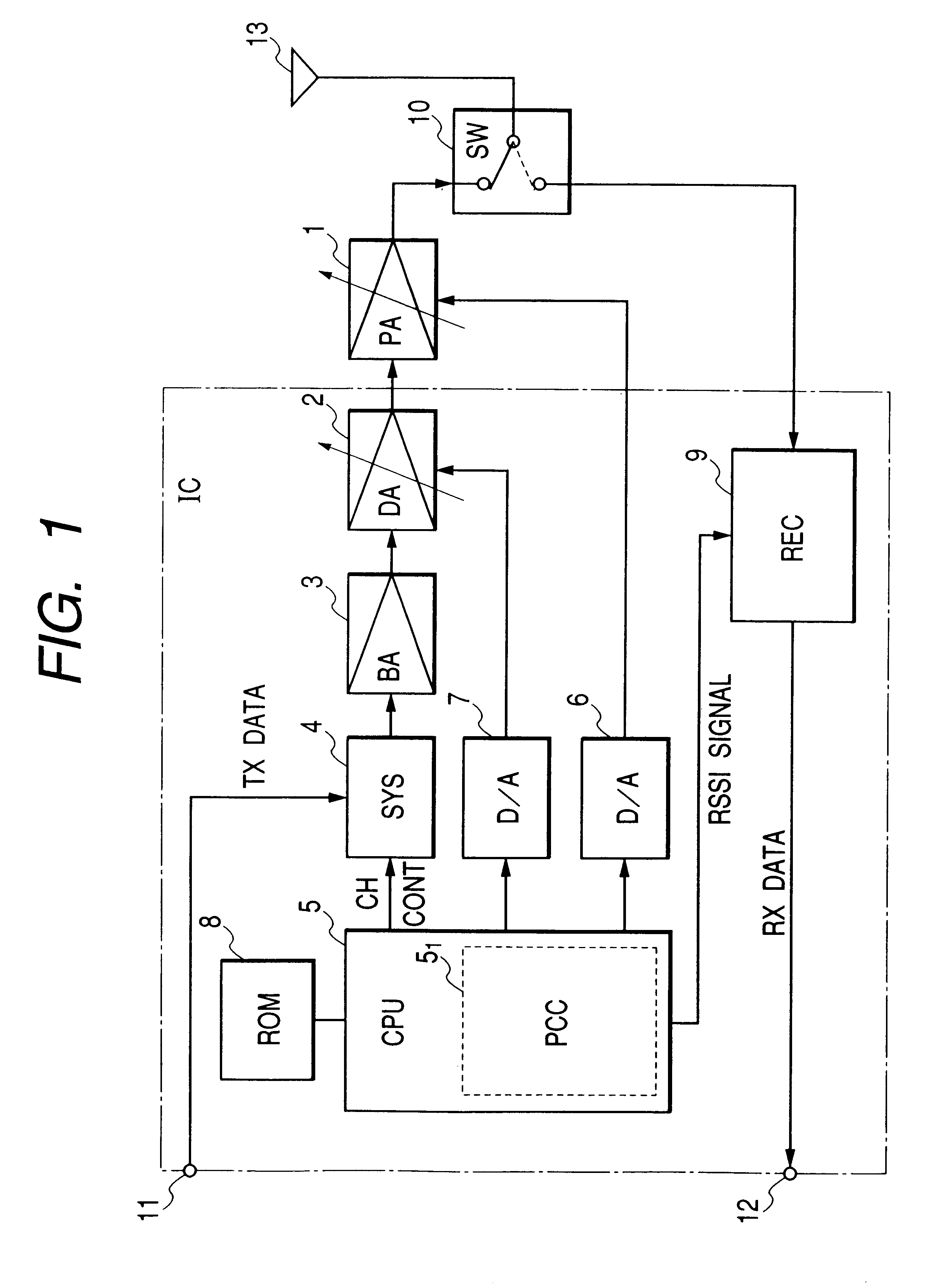
FIG. 1, which is a block diagram of the embodiment of the configuration of a transmitter adjusting output power according to the invention, shows the essential parts of a mobile telephone including the transmitter of the present invention.

As shown in FIG. 1, the mobile telephone including the transmitter embodying the invention in this mode consists of a variable-gain power amplifying stage (PA) 1, a variable-gain drive amplifying stage (DA) 2, a buffer amplifying stage (BA) 3, a synthesizer (SYS, high-frequency signal generator) 4, a controller (CPU) 5, a power controller (PCC, gain control voltage generator) 5.sub.1, a first digital-to-analog converter (D / A) 6, a second digital-to-analog converter (D / A) 7, a ROM 8, a receiver circuit (REC) 9, a transmit / receive change-over switch 10, a transmit (TX) data input terminal 11, a receive (RX) data output terminal 12, and ...


PUM


Abstract

The transmitter adjusting output power is provided with a signal generator for generating a transmit signal, a variable-gain drive amplifying stage, a variable-gain power amplifying stage for amplifying in power the amplified transmit signal, and a control voltage generator for generating a first gain control voltage for adjusting the signal gain of the variable-gain drive amplifying stage and a second gain control voltage for adjusting the signal gain of the variable-gain power amplifying stage, wherein the control voltage generator generates the second gain control voltage to adjust the signal gain of the variable-gain power amplifying stage when the required signal level is not higher than a certain fixed level and generates a first gain control voltage to adjust the signal gain of the variable-gain drive amplifying stage when the required signal level is not lower than a certain fixed level.

Description

1. Field of the InventionThe present invention relates to a transmitter adjusting output power, and more particularly to a transmitter which, driven by a battery as in the handset of a mobile telephone, adjusts output power so as to minimize the exhaustion of the power source battery when adjusting the output power of transmit signals.2. Description of the Related ArtUsually, a cordless mobile telephone, when communicating with another mobile telephone, is subject to fluctuations in the field intensity of the receive wave reaching each mobile telephone depending on the distance between the calling party's mobile telephone and the corresponding telephone relaying base and the state of the wave transmission in-between, as well as the distance between the other party's mobile telephone and the corresponding telephone relaying base and the state of the wave transmission in-between.If the field intensity of the receive wave reaching the calling party's mobile telephone is weak, the link ...

Claims


Application Information

Patent Timeline
Patent Type & Authority Patents(United States)
IPC IPC(8): H04B7/005H04B1/02H03G3/02H04B1/04H04B7/26H04L27/00H04L27/01H04L29/00H04L29/08
CPCH04W52/52H04B1/02
Inventor KANNO, SUSUMU
Owner ALPS ALPINE CO LTD
Why Eureka
Try Eureka