DC power converter having bipolar output and bi-directional reactive current transfer

a power converter and reactive current technology, applied in the direction of dc-dc conversion, power conversion systems, instruments, etc., can solve the problems of component heating, reverse current condition, and inability to perform both functions at the same time, and achieve the effect of no cross-over distortion

Inactive Publication Date: 2001-10-16
MICROCHIP TECH INC
View PDF5 Cites 84 Cited by
  • Summary
  • Abstract
  • Description
  • Claims
  • Application Information

AI Technical Summary

Benefits of technology

to provide a power converter to transform direct current, unipolar, energy to alternating current, bipolar, energy having a feature of a simple control circuit...

Problems solved by technology

Generally, however, both functions cannot be performed at the same time.
Unfortunately however, when the load on the ac output of a converter is reactive in nature, i.e. other than purely resistive, a reverse current condition can occur due to the capacitive or inductive reactive load.
Therefore when reactive loads are present, energy is wasted in the power converter as the reactive load's reverse current flow is blocked resulting in component heating, power losses and inefficiencies.
Additionally, in the case of unipolar dc to bipolar ac power converters, complex control circuits having feedba...

Method used


Image

  • DC power converter having bipolar output and bi-directional reactive current transfer
  • DC power converter having bipolar output and bi-directional reactive current transfer
  • DC power converter having bipolar output and bi-directional reactive current transfer

Examples


Embodiment Construction

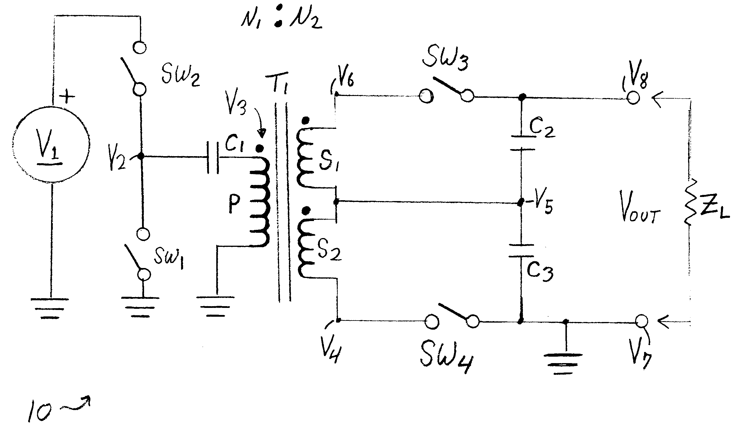
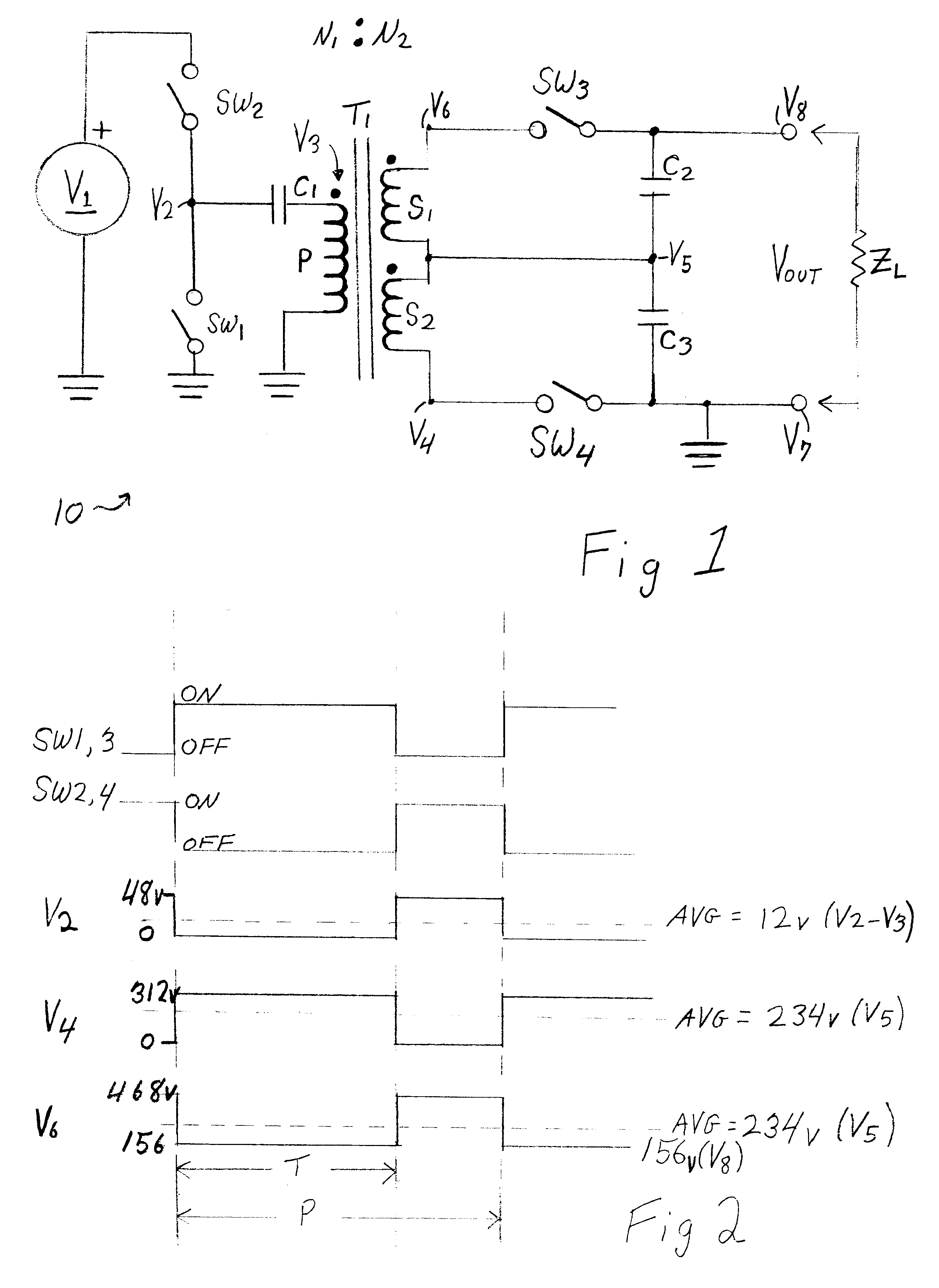
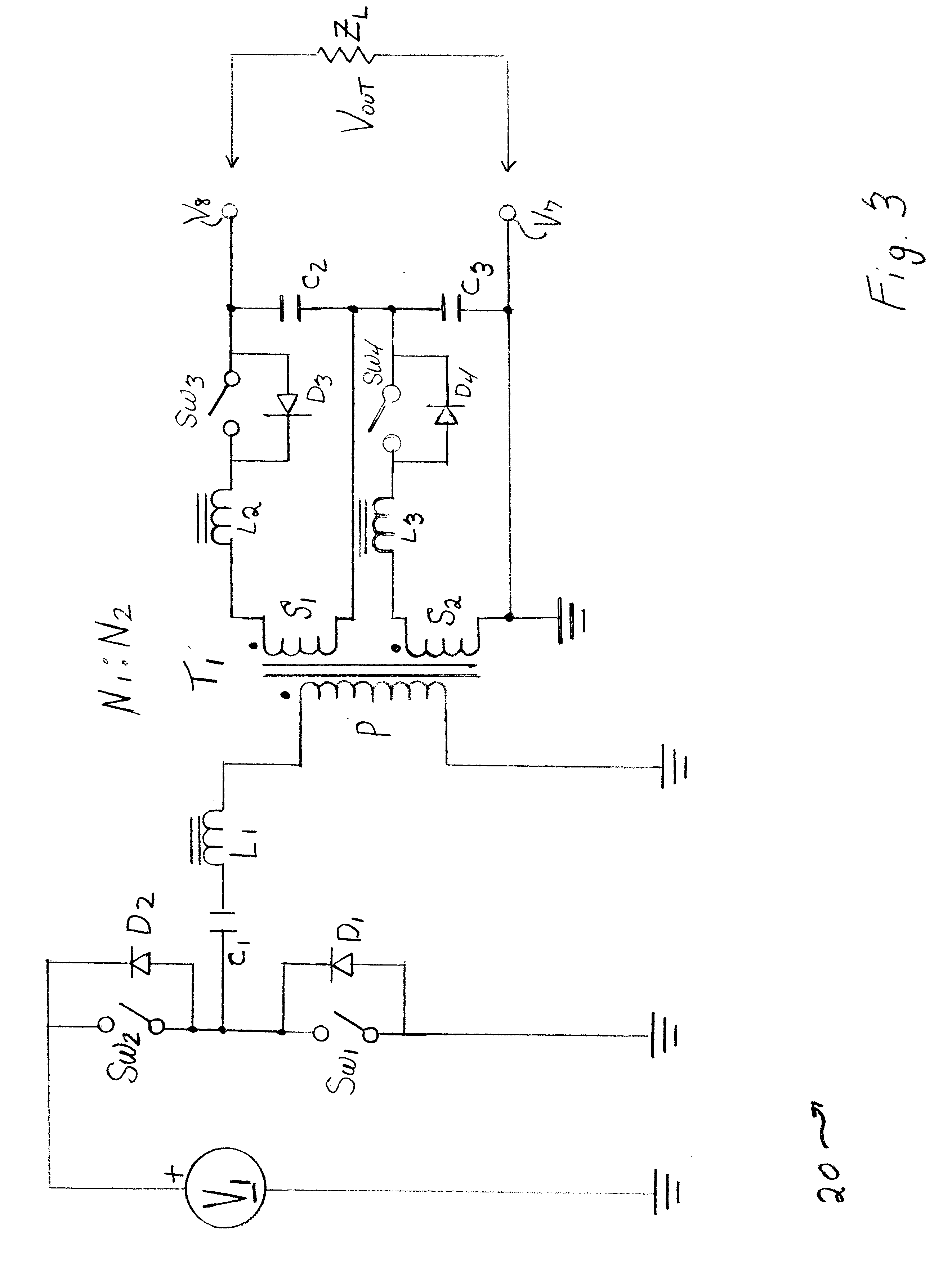
According to one aspect of the invention, a dc power converter having bipolar output and bidirectional reactive current transfer is disclosed. The dc power converter having bipolar output and bidirectional reactive current transfer comprises: a direct current source; a modulator coupled to the direct current source, the modulator comprising at least two switching means for generating a waveform pulse; a primary winding of a transformer capacitively coupled to the modulator; at least two secondary windings of the transformer magnetically coupled to the primary winding of the transformer, wherein the at least two secondary windings are bifilar wound; a first synchronous rectifier coupled to a first secondary winding of the at least two secondary windings; and a second synchronous rectifier coupled to a second secondary winding of the at least two secondary windings. The first synchronous rectifier comprises: a first switching means for interrupting a current path connected in series w...


PUM


Abstract

A dc power converter having bipolar output and bi-directional reactive current transfer is disclosed. The dc power converter comprises: a direct current source; a modulator coupled to the direct current source, the modulator comprising at least two switch means for generating a waveform pulse; a transformer primary winding capacitively coupled to the modulator; at least two transformer secondary windings magnetically coupled to the transformer primary winding; and two synchronous rectifiers coupled to a first and second secondary winding respectively of the at least two transformer secondary windings. The first and second synchronous rectifiers each comprise: a switching means for interrupting a current path connected in series with a respective secondary winding first polarity pole, and a capacitor coupled in series with the switching means. The first secondary winding second polarity pole is coupled to the second secondary winding first polarity pole such that an output voltage from the first synchronous rectifier is in electrical opposition to a second output voltage from the second synchronous rectifier.

Description

1. Field of the InventionThis invention relates to direct current to alternating current power converters, and more specifically, to a direct power converter having bipolar output and bidirectional reactive current transfer.2. Description of the Related ArtPower converters transform direct current, unipolar, energy to alternating current, bipolar, energy, or perform the reverse transformation. Generally, however, both functions cannot be performed at the same time. Unfortunately however, when the load on the ac output of a converter is reactive in nature, i.e. other than purely resistive, a reverse current condition can occur due to the capacitive or inductive reactive load. And because diodes are generally present in the power flow path of dc to ac power converters the diodes will block any attempted reverse current flow from a reactive load back into the actual dc power source. Therefore when reactive loads are present, energy is wasted in the power converter as the reactive load'...

Claims


Application Information

Patent Timeline
IPC IPC(8): H02M3/24H02M3/335
CPCH02M3/33584H02M2001/009H02M1/009
Inventor WALKER, JAMES T.
Owner MICROCHIP TECH INC
Why Eureka
Try Eureka