
Hole enlargement apparatus

a technology of enlargement apparatus and hole, which is applied in the direction of manufacturing tools, wood boring tools, transportation and packaging, etc., can solve the problems of difficult to hold in an existing hole, piece may fall into the wall where it cannot be recovered, and difficult to manufacture, etc., to achieve the effect of easy reuse, simple and inexpensive manufacturing

Inactive Publication Date: 2001-10-23
LINTHICUM LEO
View PDF6 Cites 33 Cited by
  • Summary
  • Abstract
  • Description
  • Claims
  • Application Information

AI Technical Summary

Benefits of technology

It is an object of this invention to disclose an apparatus which utilizes a thin disc, and a disc bias means to center and maintain the drill bit in an existing hole. It is an object of this invention to disclose an apparatus which is simple and inexpensive to manufacture, and lightweight to carry around. The disc bias means adequately maintains the disc in the existing hole only during use; subsequently the disc is readily removed for reuse. Additionally, compared to other technologies, the thin disc is less likely to break the drill bit if the drill bit twists out of axial alignment when the hole cutter catches in the workpiece. It is yet a final object of this invention to disclose an apparatus which employs a retention means to prevent the hole enlargement apparatus from falling into the interior of a wall, where it would be practically unretrievable.

Problems solved by technology

Compared to a simple disc, which can only partially slide into an existing hole, these are expensive to manufacture and heavy to carry around.
The problem with a simple disc however, is that if it is used to enlarge an existing hole in a wall--once the hole is cut, the disc, together with the round cut out piece may fall down into the wall where it cannot be recovered.
Another problem with a simple disc is that it is difficult to hold in an existing hole while cutting.
One problem with the tapered dowel plug is that it may vibrate loose in sheetrock or other workpieces.
Yet another problem is that the tapered dowel plug, together with the cutout piece, may fall into the interior of a wall where it cannot be recovered.

Method used


Image

  • Hole enlargement apparatus
  • Hole enlargement apparatus

Examples


Embodiment Construction

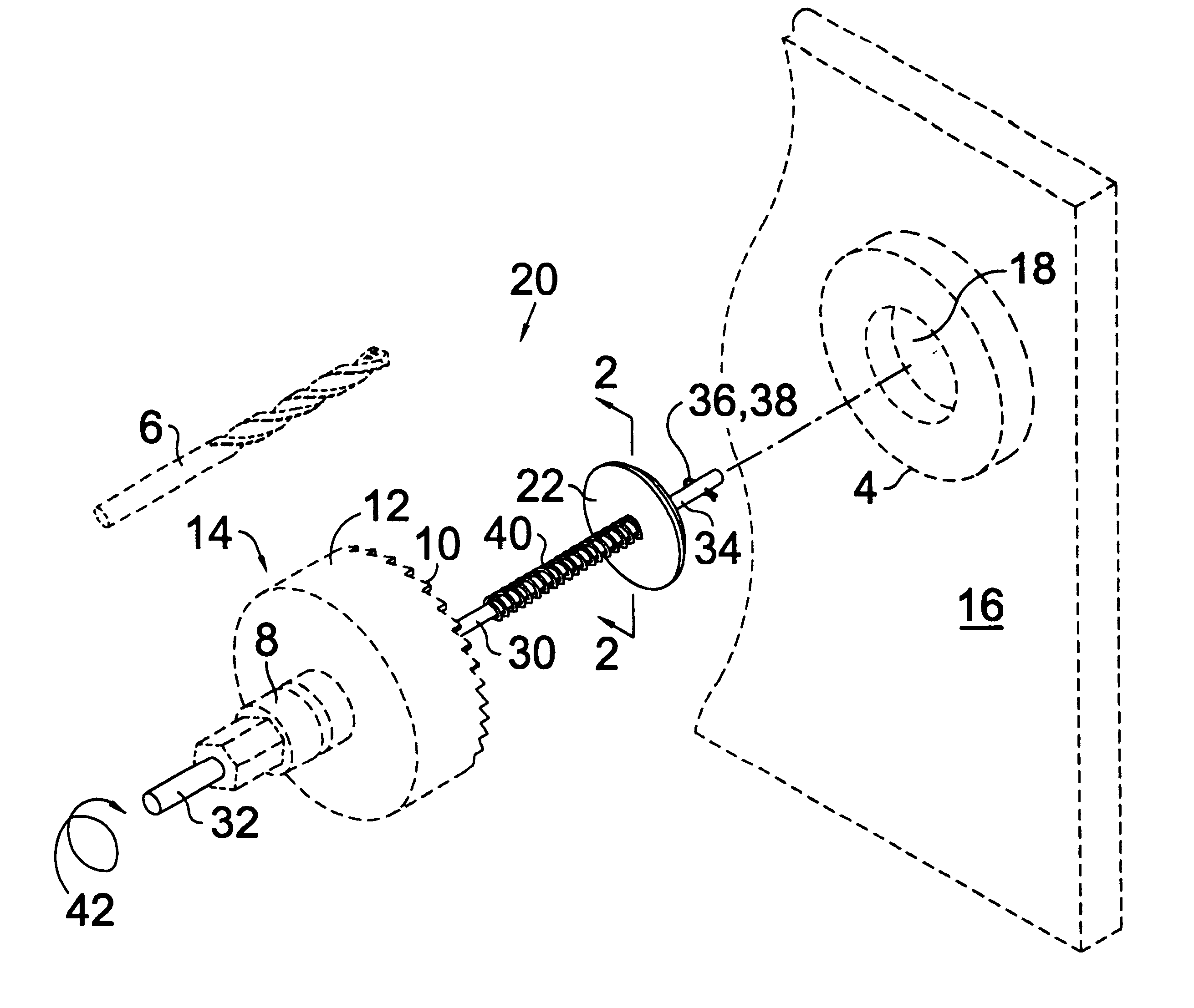
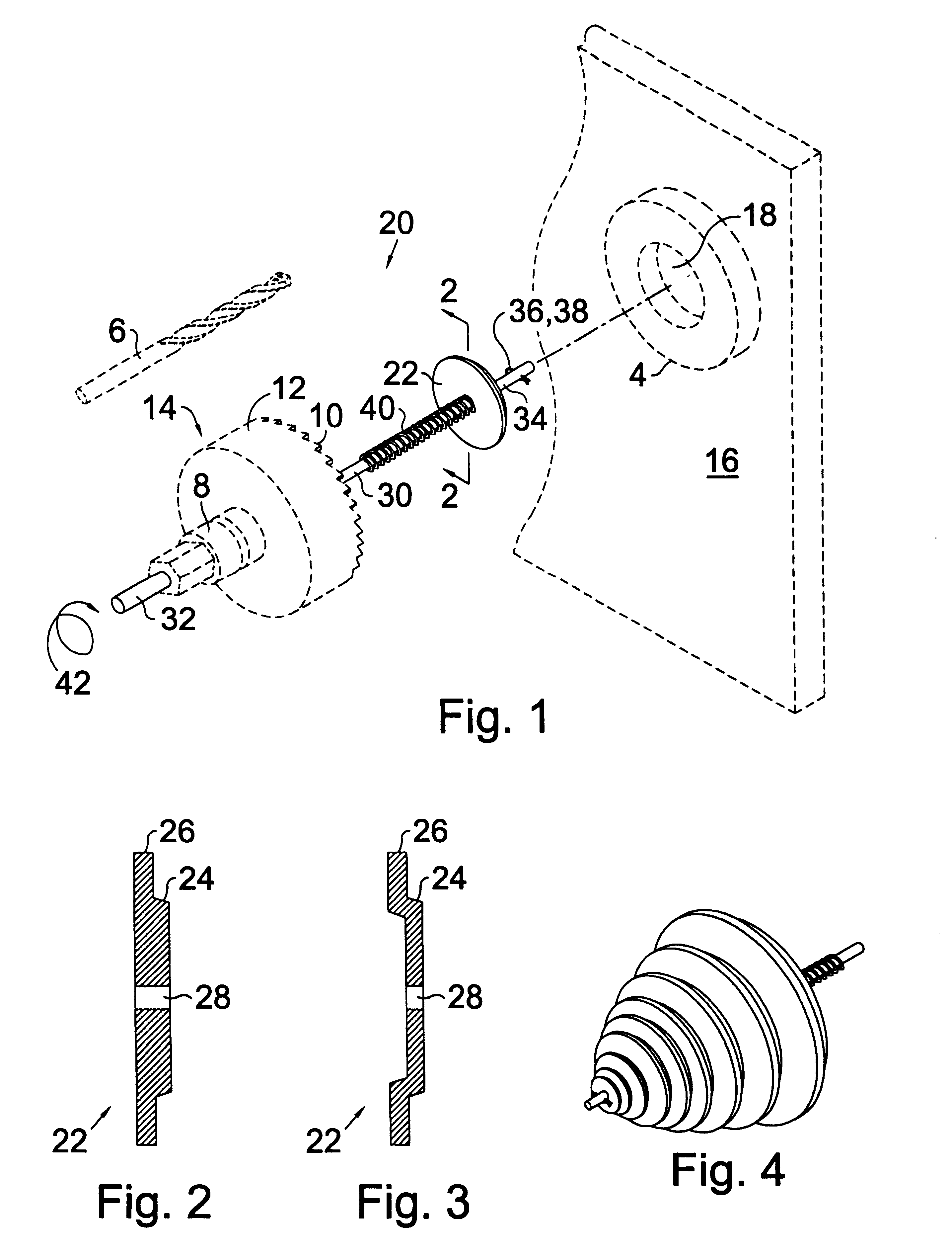
Turning now to the drawings and more particularly to FIG. 1 we have a perspective view of a hole enlargement apparatus 20 being used to enlarge an existing hole 18 in a workpiece 16. The hole enlargement apparatus 20 is used to increase the diameter of an existing hole 18. It is used in conjunction with a conventional large hole cutter 14 of the type having a cylindrical cup 12 having a toothed peripheral rim 10, a hub 8 axially secured in a bottom portion of the cup 12, and a pilot bit axially and removably secured through the hub 8 and cup 12.

FIG. 2 is a cross sectional view of a guide member 22 as viewed along line 2--2 on FIG. 1. The hole enlargement apparatus 20 comprises a guide member 22 having a disc portion 24 dimensioned to matingly fit within the existing hole 18, a rim portion 26 connected to a rear portion of the disc portion 24 which is adapted to seat on the workpiece 16 around the hole 18 to align and maintain the disc portion 24 in the hole 18, and a disc center gui...


PUM

PropertyMeasurementUnit
Diameteraaaaaaaaaa
Lengthaaaaaaaaaa
Sizeaaaaaaaaaa

Abstract

A hole enlargement apparatus which uses a simple spring biased disc to center a larger hole cutter in the existing hole and a disc retention means to ensure that the disc does not fall unretrievably into the enlarged hole. The apparatus is used in conjunction with a conventional large hole cutter of the type having a toothed cylindrical cup, a hub axially secured in a bottom portion of the cup, and a pilot bit axially and removably secured through the hub and cup. The hole enlargement apparatus comprises: a guide member having a disc portion dimensioned to matingly fit within the existing hole, a rim portion connected to a rear portion of the disc portion adapted to seat on the workpiece, and a disc center guide opening dimensioned to slidingly accept a shaft the diameter of the pilot bit; a drill bit replacement shaft having a hub end portion and an opposite disc end portion; a cotter pin carried by the disc end portion of the drill replacement shaft to prevent the guide member from sliding off the disc end portion of the shaft; and, a spring to bias and maintain the disc portion in the existing hole.

Description

This invention relates to the problem of guiding a hole cutter when enlarging an existing hole. More particularly this invention relates to the use of a simple disc which centers the larger hole cutter in the existing hole and a disc retention means which ensures that the disc does not fall unretrievably into the enlarged hole.The inventor is an electrician who has been involved in residential construction and remodelling. When the need arises to enlarge an existing hole some means of maintaining the pilot drill in the center of the existing hole must be provided for.There are a number of relatively elaborate devices to center a pilot drill in an existing hole. Compared to a simple disc, which can only partially slide into an existing hole, these are expensive to manufacture and heavy to carry around. The problem with a simple disc however, is that if it is used to enlarge an existing hole in a wall--once the hole is cut, the disc, together with the round cut out piece may fall down...

Claims


Application Information

Patent Timeline
IPC IPC(8): B23B51/04
CPCB23B51/0426B23B51/0453Y10T408/895Y10T408/558Y10T408/03Y10T408/8923
Inventor LINTHICUM, LEO
Owner LINTHICUM LEO
Learn More