Engine mounting of an exhaust gas recirculation valve

a technology of exhaust gas recirculation and engine, which is applied in the direction of machines/engines, mechanical equipment, non-fuel substance addition to fuel, etc., can solve the problems of harsh operating environment, wide temperature extremes and vibrations, and achieve the effect of reducing the number of parts required, and efficiently integrating the valve/engine combination

Inactive Publication Date: 2001-11-06
SIEMENS CANADA LTD
View PDF3 Cites 16 Cited by
  • Summary
  • Abstract
  • Description
  • Claims
  • Application Information

AI Technical Summary

Benefits of technology

The present invention relates generally to an improvement in mounting an EGR valve, especially an electric EGR valve of the type described herein, directly on an engine, an engine cylinder head in particular. Such a mounting can serve to reduce the number of parts required in an EGR valve, because certain structure in the engine itself co

Problems solved by technology

When an EGR valve is engine-mounted, it is exposed to a harsh operati

Method used


Image

  • Engine mounting of an exhaust gas recirculation valve
  • Engine mounting of an exhaust gas recirculation valve

Examples


Embodiment Construction

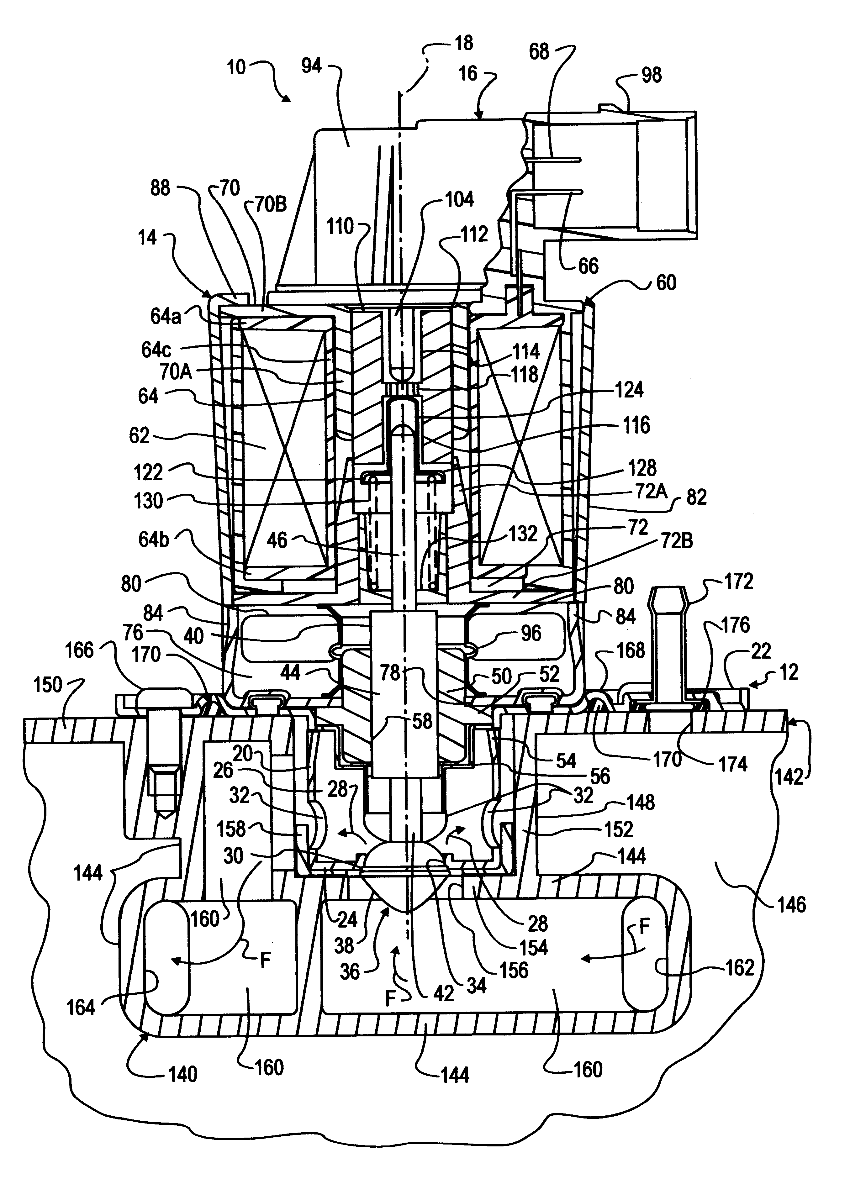
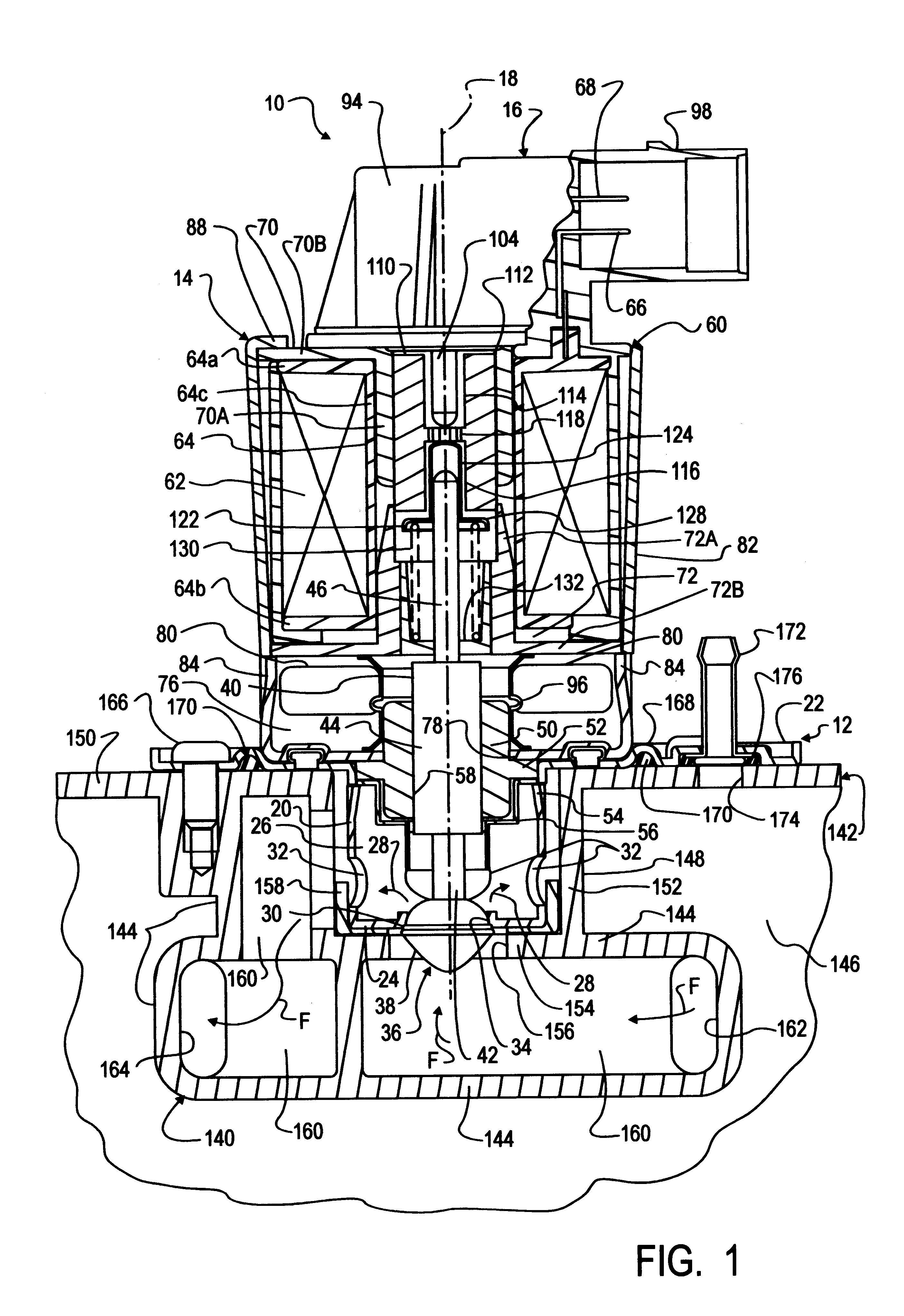
FIG. 1 illustrates an engine-mounted electric EGR valve (EEGR valve) 10 embodying principles of the present invention. Because certain features of EEGR valve 10 are important to its mounting on an engine, valve 10 will first be described in detail. The valve comprises valve body structure composed of a stamped metal base 12, a generally cylindrical metal shell 14 disposed on top of base 12, and a non-metallic cap 16 atop shell 14. FIG. 1 also shows the internal construction of valve 10 which may, for convenience, be described with reference to an imaginary longitudinal axis 18 that is generally vertical when the valve is mounted on an engine as shown.

Base 12 comprises a central cylindrical cup 20 coaxial with axis 18 and a generally circular radial flange 22 that adjoins the rim of cup 20. Cup 20 itself comprises a bottom wall 24 and a side wall 26 that extends between bottom wall 24 and flange 22. Cup 20 defines a main internal exhaust gas passage 28 through EEGR valve 10. That pas...


PUM


Abstract

An internal combustion engine cylinder head (142) has an exterior wall that contains a walled compartment (140). A wall of that compartment is exposed to an internal coolant passage (146) through which liquid coolant circulates. An exhaust gas passageway (160) running through the compartment has an exhaust gas entrance (162) into the compartment and an exhaust gas exit (164) from the compartment. The compartment comprises a receptacle (148) that intersects the exhaust gas passageway between the entrance and the exit. An EGR valve (10) disposed on the exterior wall comprises a base (12) that has an inlet port (30) and an outlet port (32) and that is disposed within the receptacle with the inlet port open to the entrance via the passageway and the outlet port open to the exit via the passageway. As hot exhaust gas is recirculated, coolant that circulates through the coolant passage aids in limiting peak temperatures to which the valve may be subjected.

Description

FIELD OF THE INVENTIONThis invention relates generally to automotive emission control valves. More specifically it relates to an engine mounting of an exhaust gas recirculation (EGR) valve.BACKGROUND OF THE INVENTIONControlled engine exhaust gas recirculation is a commonly used technique for reducing oxides of nitrogen in products of combustion that are exhausted from an internal combustion engine to atmosphere. A known EGR system comprises an EGR valve that is controlled by an electric circuit in accordance with various engine operating conditions to regulate the amount of engine exhaust gas that is recirculated to the induction fuel-air flow entering the engine for combustion so as to limit the combustion temperature and hence reduce the formation of oxides of nitrogen.When an EGR valve is engine-mounted, it is exposed to a harsh operating environment that includes wide temperature extremes and vibrations. Exhaust emission requirements impose more stringent demands for improved co...

Claims


Application Information

Patent Timeline
IPC IPC(8): F02M25/07
CPCF02M25/0703F02M25/0747F02M25/079F02M25/0795F02M25/0756F02M25/0772Y02T10/121F02M26/12F02M26/41F02M26/48F02M26/53F02M26/68F02M26/73
Inventor COOK, JOHN EDWARDHUSSEY, SCOTT
Owner SIEMENS CANADA LTD
Why Eureka
Try Eureka