Assembly having lancet and means for collecting and detecting body fluid

a technology of body fluid and lancet, which is applied in the field of assembly having lancet and means for collecting and detecting body fluid, can solve the problems of cumbersome operation, risk of infection by the blood that adheres to the tourniquet, and the difficulty of sterilization of the puncture needle, so as to achieve efficient introduction

Inactive Publication Date: 2001-11-13
TERUMO KK
View PDF16 Cites 609 Cited by
  • Summary
  • Abstract
  • Description
  • Claims
  • Application Information

AI Technical Summary

Benefits of technology

The present invention provides an assembly for use with a body fluid-monitoring system wherein the lancet (the puncture needle) has been sterilized and the sterilized condition is maintained until its use while adverse effects caused by the sterilization of the lancet such as the adverse effects which might be induced in the reagents impregnated in the test strip are avoided. Use of the assembly according to the present invention ensures safe measurement due to the sterilized conditions maintained until the use of the lancet and simple and reliable attachment and detachment of the lancet and test paper units since both units can be simultaneously handled.
The body fluid-collecting and detecting unit of the present invention has a body fluid guide which enables efficient introduction of the body fluid into its interior, and the measurement can be accomplished by lancing and collecting minimum amount of the body fluid. Therefore, milking and massaging of the lanced site is no longer necessary.

Problems solved by technology

In the system of the type disclosed in JP-A 6-339473, the lancet mechanism and the detection mechanism are separate, and the lancet unit including the puncture needle and the detection unit including the test strip should be separately mounted on the monitoring system, and the operation is cumbersome.
In this glucose meter, collection of the required amount of the blood is enabled by the use of the tourniquet, and as a consequence, this system is associated with the risk of infection by the blood that adheres to the tourniquet when the finger is pulled out through the tourniquet after the blood collection.
In JP-A 9-276235, the puncture needle and the electrode coated with the enzyme ink are arranged adjacent to each other, and sterilization of the puncture needle should be quite difficult once the cartridge is accommodated in the cartridge.
Assembly of the cartridge after sterilizing the puncture needle, on the other hand, is quite nonproductive since a clean room is required for such operation.
This system also suffers from the difficulty of sterilization as in the case of JP-A 9-276235, and sterilization of the unit before its use is associated with the risk of denaturing of the reagents immobilized on the test strip.
Therefore, it has been difficult to deliver a product wherein sterilization of the puncture needle is maintained until the use of the product.
Such change of the device should be conducted while the blood is flowing out from the punctured site, and this procedure is associated not only with inconvenience of the operation but also with unfavorable sanitary conditions.
The type wherein the blood is dropped on the test strip in the cartridge is associated with the problem of inconsistent measurement value since the time interval between the blood collection and mounting of the cartridge is not constant.
Such reduction in the volume of the capillary results in the reduced size of the inlet of the capillary, and introduction into the capillary of the blood becomes difficult.
In addition, when the area surrounding the capillary inlet erroneously becomes in contact with the blood, sucking of the blood into the capillary is impeded.
Moreover, when such reservoir is in the same plane as the main body of the cartridge, there is always some risk of blood leakage from the gap between the finger and the reservoir due to the finger print unless the finger is very tightly pressed against the cartridge, and such blood leakage is likely to result in the blood adhesion to the back surface of the cartridge, and also, increase in the amount of the blood necessary for the measurement.
On the other hand, when the blood volume collected by the lancet is insufficient, the blood will never reach the test strip.
The measurement is, therefore, unreliable and unsanitary.
The body fluid guide 34 of an inappropriate shape will also result in an insufficient sucking of the body fluid into the flow path 33, and the amount of body fluid required for the measurement will be increased to result in the increased burden of the patient.
The body fluid guide 134 of an inappropriate shape will also result in an insufficient sucking of the body fluid into the flow path 133, and the amount of body fluid required for the measurement will be increased to result in the increased burden of the patient.

Method used


Image

  • Assembly having lancet and means for collecting and detecting body fluid
  • Assembly having lancet and means for collecting and detecting body fluid
  • Assembly having lancet and means for collecting and detecting body fluid

Examples


first embodiment

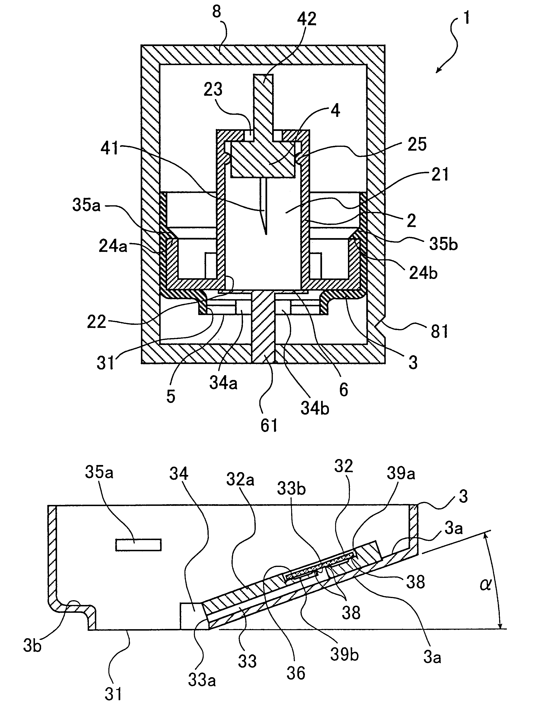
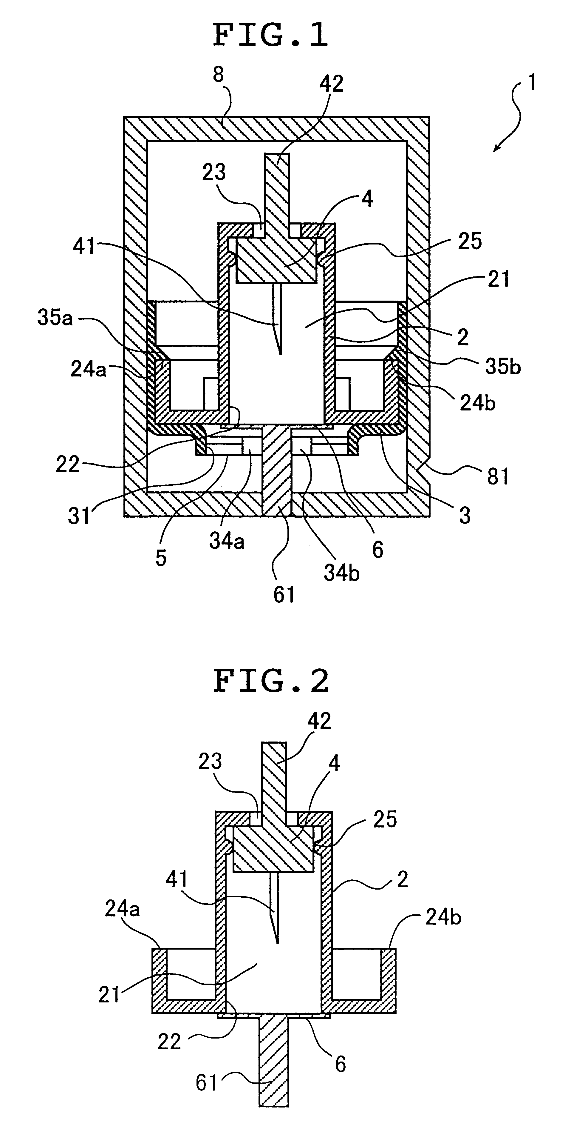
FIG. 1 is a lateral cross sectional view of an assembly 1 according to the present invention.

The assembly 1 comprises a first housing 2 accommodating the lancet 4 and a housing 3 accommodating the body fluid-collecting and detecting means.

FIG. 2 is a cross sectional view of the lancet section of FIG. 1. The first housing 2 has a sleeve 21 in which the lancet 4 is movably accommodated. The sleeve 21 has a first opening 22 at its distal end and a proximal opening 23 at its proximal end.

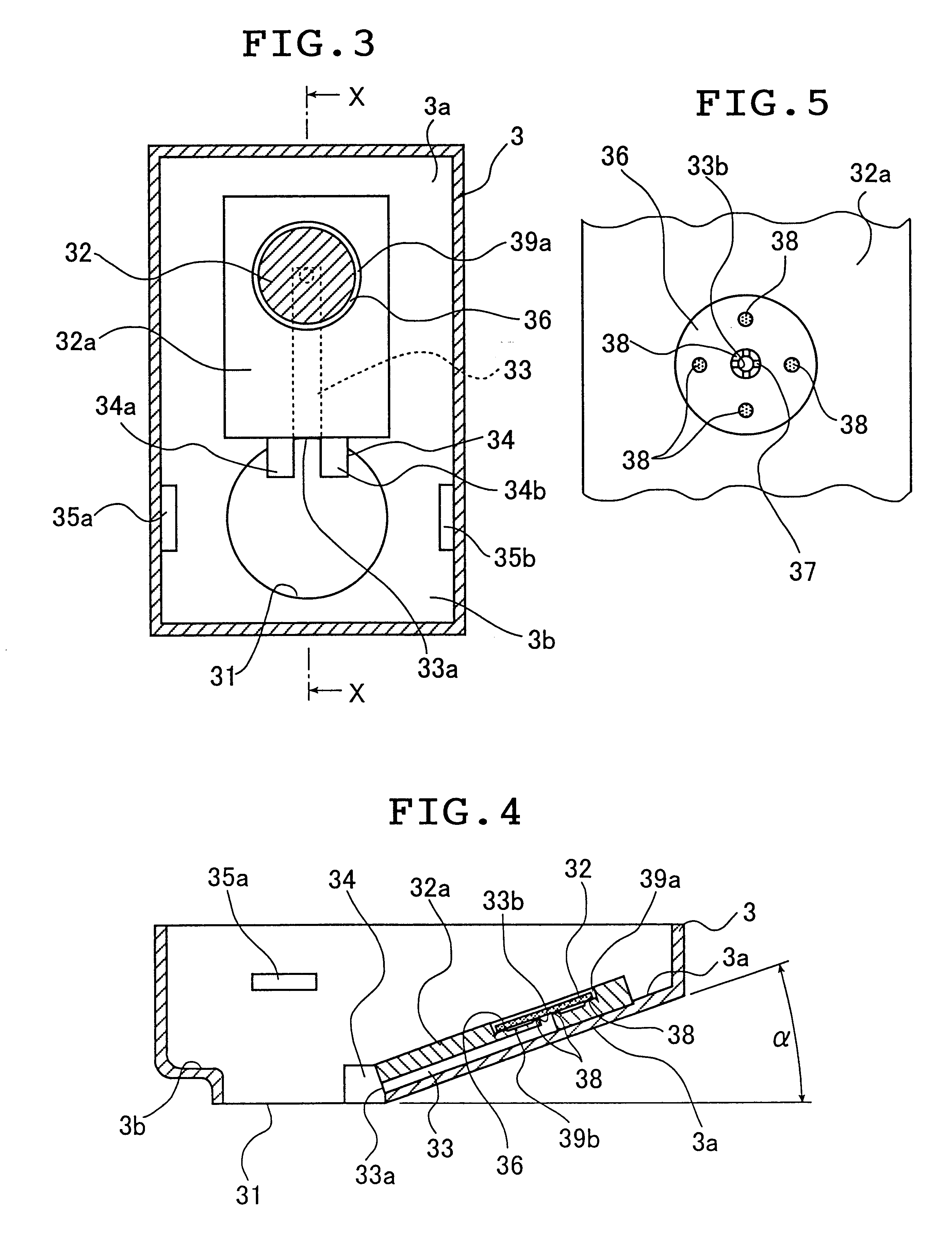
FIG. 3 is a plan view of the body fluid-collecting and detecting section, and this section comprises detection means 32 and the housing 3 having a second opening 31 formed therewith to allow introduction of the body fluid to the detection means 32.

FIG. 4 is a cross sectional view taken along lines X--X of the second housing 3 in FIG. 3.

The first housing 2 and the second housing 3 are fixedly secured to each other to constitute the assembly 1 such that the first opening 22 and the second opening 31 surro...

second embodiment

It should be noted that, in the embodiment as described above, the test strip housing 32a is formed on the bottom surface 3a. When the second housing 3 has a sleeve which fixedly receive the first housing 2 in its interior, the space required for the second housing 3 will be reduced. Such embodiment will be described later as the

The assembly 1 is preferably sealed in a protective shield 8 after its assembly, namely, after assembling to form the distal opening 5 the first housing 2 having the sealed sleeve 21 and the sterilized puncture needle 41 enclosed therein and the second housing 3 having the body fluid-detecting means. The structure of the protective shield 8 is not limited as long as the assembly 1 of particular embodiment can be sealed in its interior. The embodiment of the protective shield 8 shown in the drawings is the one in the form of a sheet, and the protective shield 8 of this embodiment can be removed immediately before the use by tearing the sheet from the notch 81...


PUM


Abstract

An assembly to be detachably mounted on a body fluid monitoring system is provided. The assembly has a lancet and a device for collecting and detecting a body fluid. The lancet has a puncture needle. In this assembly, the puncture needle is maintained in sterilized conditions until its use, and the sterilization can be conducted with no adverse effects on the detection device. A readily sterilizable lancet unit and a body fluid-collecting and detecting unit adapted for use in such an assembly as well as a body fluid-monitoring system including such an assembly are also provided. The assembly comprises a first housing having a sleeve which movably accommodates the lancet in its interior, and a second housing having the body fluid detection device. The first housing and the second housing share an opening. The lancet is sterilized before the assembly. The body fluid-collecting and detecting section has a body fluid guide on the periphery of the inlet.

Description

This invention relates to an assembly which is detachably mounted to a body fluid-monitoring system for laboratory testing of a body fluid such as blood, wherein the assembly has a lancet and a means for collecting and detecting the body fluid. This invention also relates to a body fluid-collecting and detecting unit for use in such assembly, and a body fluid-monitoring system having such an assembly detachably mounted thereto.With the increase in the number of patients suffering from diabetes, self-monitoring of blood glucose wherein the patient can daily monitor his or her blood glucose level has been highly recommended. In view of such situation, various systems wherein a lancet and a glucose meter are integrated have been disclosed for ease of the blood glucose self-monitoring and to enable hygienic measurement. Such systems are disclosed, for example, in JP-A 6-339473, JP-A 9-276235, and U.S. Pat. No. 4,787,398.In the system of the type disclosed in JP-A 6-339473, the lancet me...

Claims


Application Information

Patent Timeline
Patent Type & Authority Patents(United States)
IPC IPC(8): A61B5/15
CPCA61B5/1411A61B5/150022A61B5/150358A61B5/150412A61B5/15113A61B5/1519A61B5/157A61B2562/0295A61B5/150213A61B5/150503A61B5/150587A61B5/15061A61B5/15117
Inventor NISHIKAWA, HISAOSONODA, KOUICHITAKINAMI, MASAOMORIKAWA, NAOKI
Owner TERUMO KK
Why Eureka
Try Eureka