Slider-pull-assembling unit

a technology of sliding pull and assembly unit, which is applied in the direction of funeral devices, hoisting equipment, clothes making devices, etc., can solve the problems of slipping out, pull-assembling units, and inability to carry out assembly at a high speed, and achieve the effect of simple structure and high speed

Inactive Publication Date: 2001-11-20
YKK CORP
View PDF4 Cites 4 Cited by
  • Summary
  • Abstract
  • Description
  • Claims
  • Application Information

AI Technical Summary

Benefits of technology

is to provide a slider-pull-assembling unit having a simple structure and capable of assembling a pull onto a slider body accurately and securely at a high speed.

Problems solved by technology

As a result, it takes a long time to complete an assembly of the pull onto the slider body, so that the assembly cannot be carried out at a high speed.
Further, in the slider-pull-assembling unit disclosed in the aforementioned Japanese Patent Publication No. 7-79726, because the slider-body pusher advances and moves back for every assembly of the pull onto the slider body, it has the same problem as described above.
Further, there is a problem common to the pull-assembling units of these patent publications.
This slip-out is more likely to occur as the unit processing speed is accelerated.
In the pull-assembling unit disclosed in the aforementioned Japanese Utility Model Publication No. 5-29603, not only a structure of the holding member is complicated, but also it is difficult to keep an accurate timing between the rotation disk and the holding member and an accurate timing of complicated actuation of the holding member itself for a long time.
Further, it takes considerably a long time for maintenance and control of these components.

Method used


Image

  • Slider-pull-assembling unit
  • Slider-pull-assembling unit
  • Slider-pull-assembling unit

Examples


Embodiment Construction

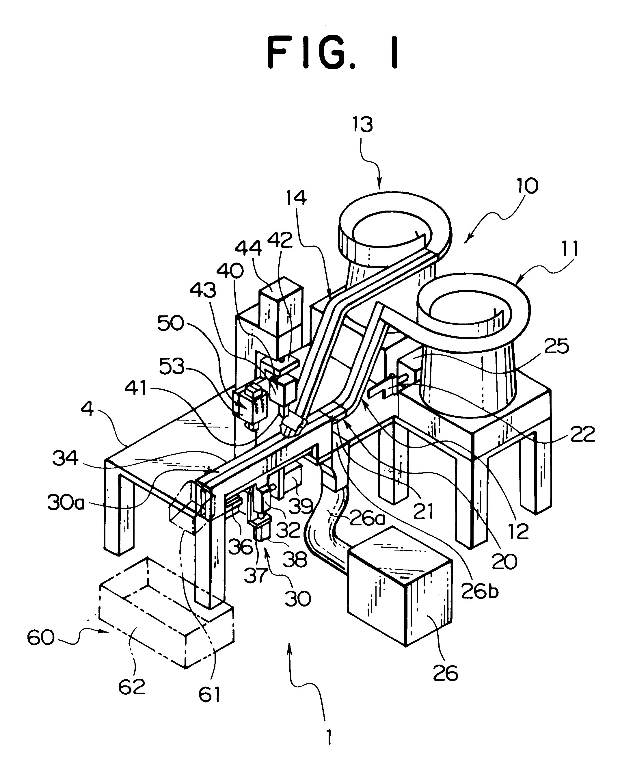
Hereinafter, embodiments of the present invention will be described in detail with reference to the accompanying drawings. FIG. 1 schematically shows an entire structure of a slider-pull-assembling unit, which is a typical embodiment of the present invention.

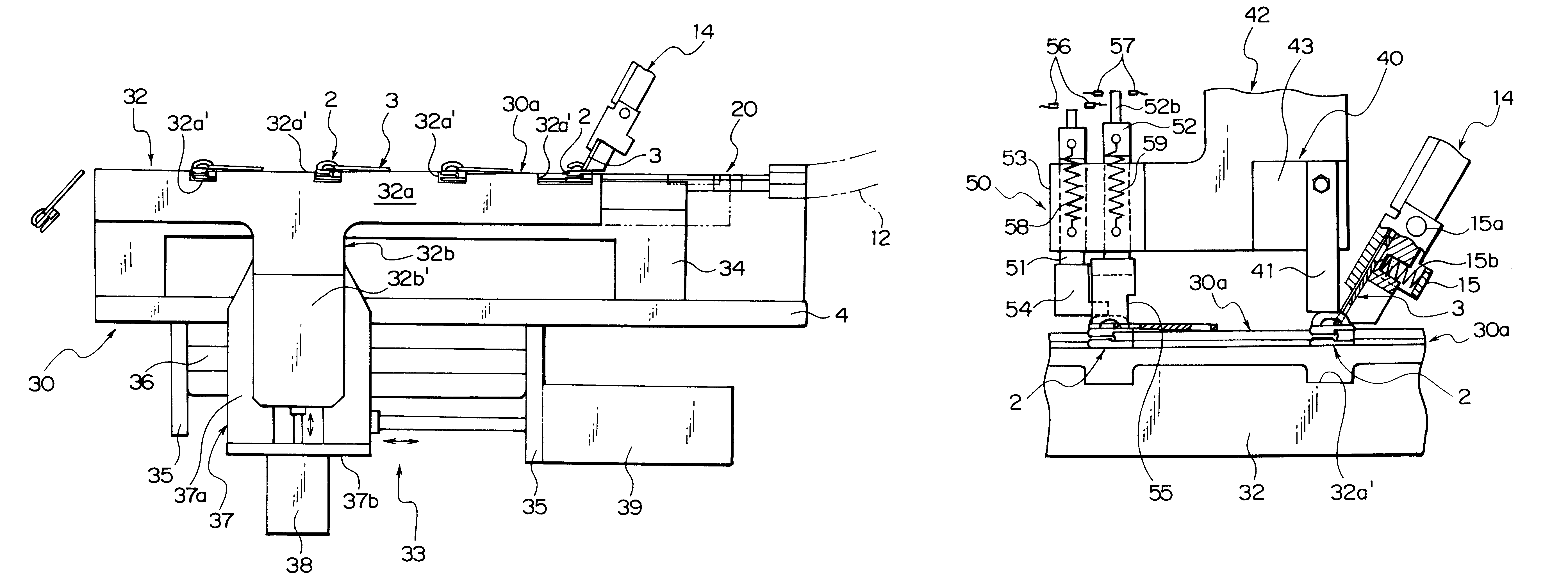
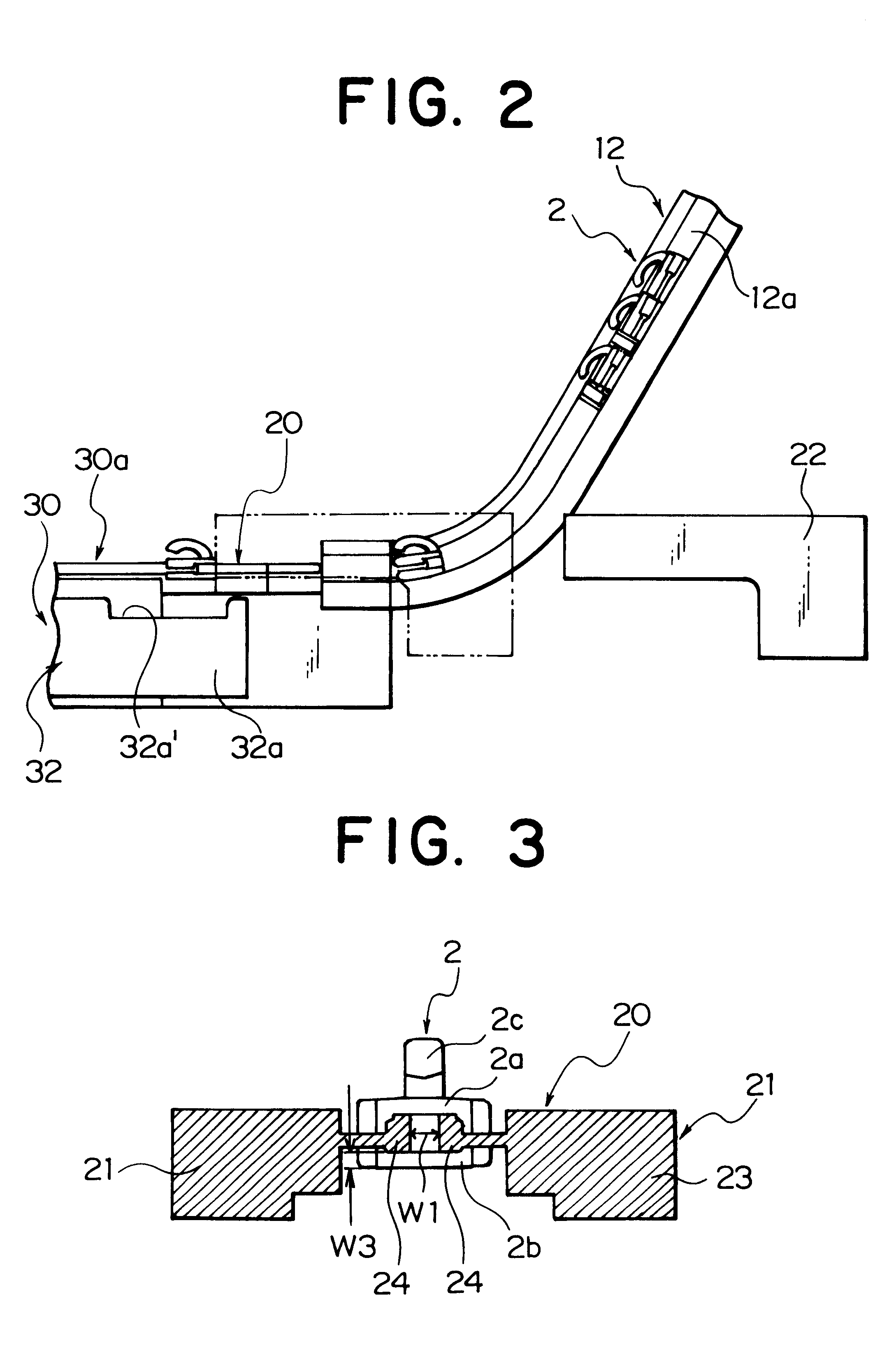
In the slider-pull-assembling unit 1 of the embodiment shown here, mainly a slider-body-and-pull-supply section 10, a burr-removing section 20 for a slider body 2, a slider-transportation section 30, a slider-body-pull-attachment-lug crimping section 40, a slider-inspecting section 50, a slider-discharge section 60 are arranged in succession at a predetermined pitch.

The slider-body-and-pull-supply section 10 comprises a slider-body feeder 11, a slider-body chute 12 extending from the slider-body feeder 11 to the burr-removing section 20, a pull feeder 13, and a pull chute 14 extending from the pull feeder 13 to the slider-transportation section 30. The slider-body chute 12 is linearly disposed so as to obliquely intersect the sl...


PUM

PropertyMeasurementUnit
angleaaaaaaaaaa
timeaaaaaaaaaa
speedaaaaaaaaaa

Abstract

In a pull-assembling unit for automatically assembling a pull onto a slider body of a slide fastener, a slider transporting means includes a slider-body-transportation plate member having rectangular notch portions spaced at intervals of plural assembling sections along a top end edge thereof, each for accommodating the slider body. The slider-body-transportation plate member is adapted to be actuated in the slider-transportation path so as to draw a rectangular trajectory in a vertical plane. An actuation upper limit position of a top end of the rectangular notch portion is set to be above a slider-body-placing surface of the slider-transportation path and an actuation lower limit position of the top end of the notch portion is set to be at a retreat position below the slider-body-placing surface. Therefore, the slider-pull-assembling unit has a simple structure and is capable of assembling a pull onto a slider body accurately and securely at a high speed.

Description

1. Field of the InventionThe present invention relates to a slider-pull-assembling unit for automatically assembling a pull onto a slider for opening / closing a slide fastener. More particularly, it relates to a slider-pull-assembling unit which enables effective transportation of sliders and assembly of a pull thereto in accordance with assembling steps.2. Description of the Related ArtConventionally, a unit for automatically assembling a pull onto a slider body by inserting an annular connecting portion of the pull into an opening formed in part of a pull-attachment lug of the slider body and then crimping the pull-attachment lug to close the opening has been already reduced to practice. Such a unit has been disclosed in, for example, Japanese Patent Publication No. 1-25563, Japanese Utility Model Publication No. 5-29603, Japanese Patent Publication No. 7-79726.In the slider-pull-assembling units disclosed in the Japanese Patent Publication No. 1-25563 and Japanese Patent Publicati...

Claims


Application Information

Patent Timeline
Patent Type & Authority Patents(United States)
IPC IPC(8): A44B19/42F16H55/36B29D5/00
CPCA44B19/42Y10T29/53052Y10T29/5101Y10T29/53291Y10T29/49782A61G17/007A61G17/08A61G17/047A61G17/036
Inventor FUNAYA, KAZUHIROMARUYAMA, YUKIO
Owner YKK CORP
Why Eureka
Try Eureka