Ferroic transducer

Inactive Publication Date: 2001-11-27
CHARLES TARK DRAPER LAB INC THE
View PDF13 Cites 59 Cited by
  • Summary
  • Abstract
  • Description
  • Claims
  • Application Information

AI Technical Summary

Benefits of technology

The invention results from the realization that a ferroic transducer which is simpler and much more sensitive can be achieved by placing all the electrodes on the same side of the ferroic material such as ferroelectric, pyroelectric or electrostrictive material and u

Problems solved by technology

Typically these devices at least in thin film form have low sensitivity.
However, this introduces a number of problems including wasted space, complicated fabrication and increased st

Method used


Image

  • Ferroic transducer
  • Ferroic transducer
  • Ferroic transducer

Examples


Embodiment Construction

Other objects, features and advantages will occur to those skilled in the art from the following description of a preferred embodiment and the accompanying drawings, in which:

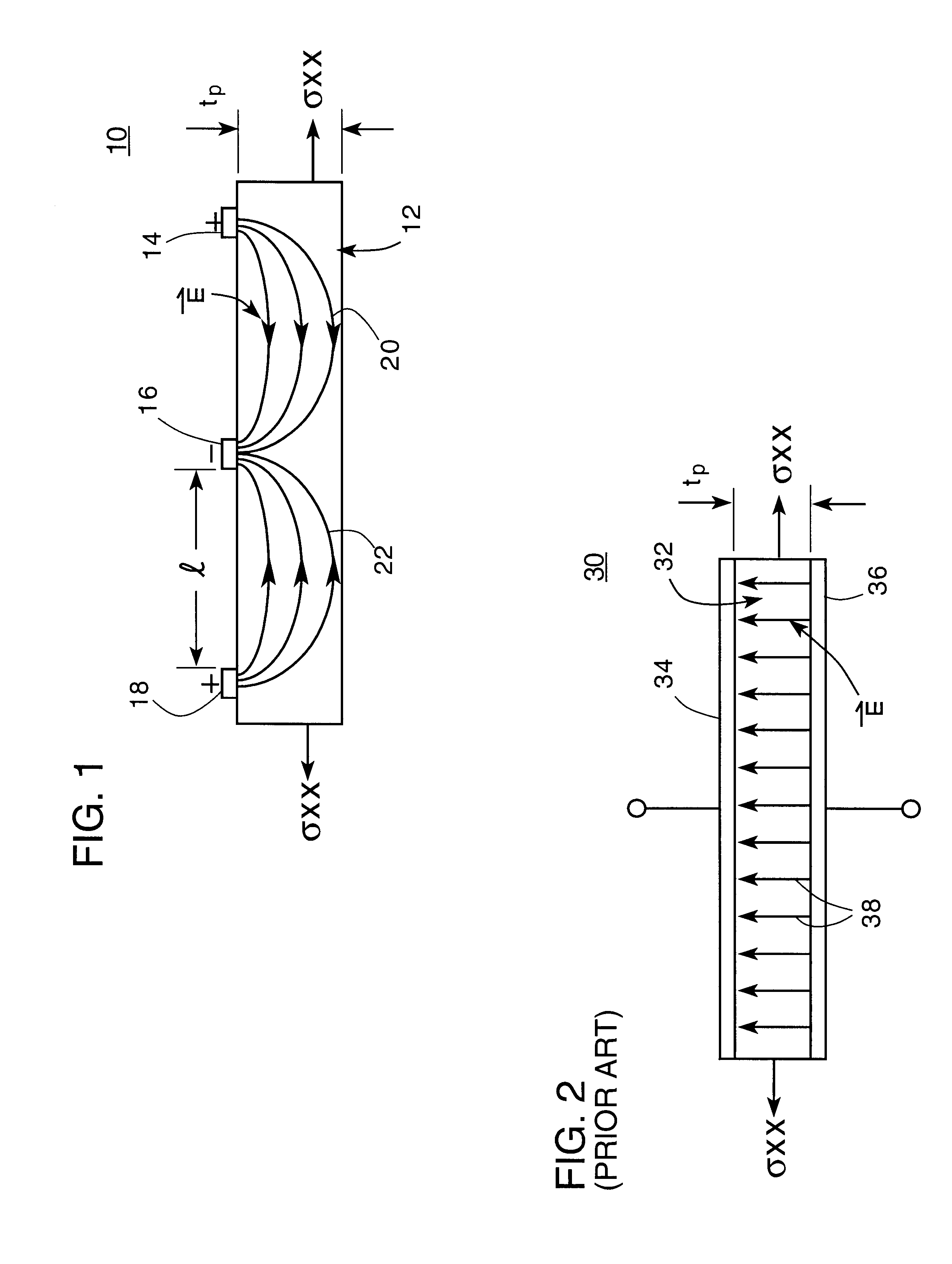
FIG. 1 is a schematic side elevational view of an improved ferroic transducer according to this invention showing the relationship of the electrodes and substantially planar electric field;

FIG. 2 is a view similar to FIG. 1 of a prior art device;

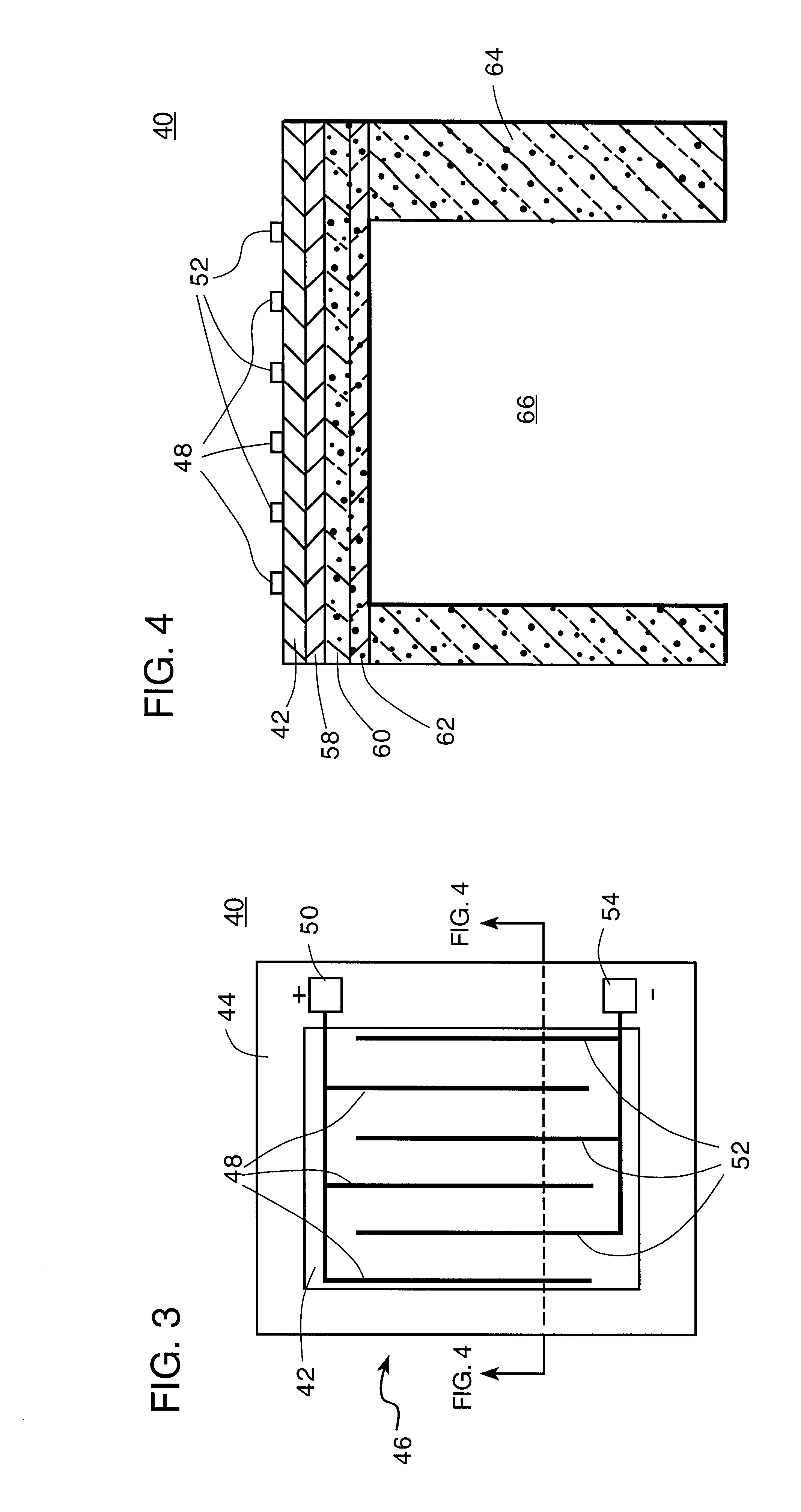
FIG. 3 is a top plan view of an interdigitated electrode ferroic transducer according to this invention;

FIG. 4 is a schematic side elevational sectional view along line 4--4 of FIG. 3;

FIG. 5 is a top view of a device similar to FIG. 4 having concentric interdigitated electrodes;

FIG. 6 is a view similar to FIG. 4 of an interdigitated electrode ferroic infrared receiver transducer according to this invention;

FIG. 7 is a schematic diagram showing the drive circuit and sense electronics for use with an interdigitated electrode ferroic transducer in accordance with this inve...


PUM


Abstract

An interdigitated electrode ferroic transducer includes a film of ferroic material electrically polarized substantially in the plane of the film; and a set of interdigitated electrodes including at least two electrodes spaced from one another on the same side of the film and disposed at the termini of the polarization field.

Description

This invention relates to an improved ferroic transducer, and more particularly to such a transducer with interdigitated electrodes.BACKGROUND OF INVENTIONConventional ferroic transducers employ the ferroic material between a pair of electrodes on opposite sides of the transducer which use the electric field across the thickness of the transducer to convert the acoustic signals into electrical signals and vice versa for underwater or medical sonar use. The term ferroic when used herein includes ferroelectric, pyroelectric and electrostrictive materials. Another application is as a bolometer array for IR imaging using the pyroelectric coefficient of the material. Typically these devices at least in thin film form have low sensitivity. In addition they have high capacitance in the neighborhood of 10-100 pf which is not well matched with present CMOS technology that has input capacitances as low as 0. 1 pf or even less. One attempt to increase sensitivity and decrease capacitance parti...

Claims


Application Information

Patent Timeline
IPC IPC(8): H01L41/00H01L37/00H01L41/047H01L37/02
CPCH01L27/20H01L37/02H01L41/047H01L41/0973H10N39/00H10N15/10H10N30/87H10N30/2047
Inventor BERNSTEIN, JONATHAN J.
Owner CHARLES TARK DRAPER LAB INC THE
Why Eureka
Try Eureka