Method of optical signal transmission with reduced degradation by non-linear effects

a nonlinear effect and optical signal technology, applied in multiplex communication, wavelength-division multiplex systems, instruments, etc., can solve problems such as troublesome cross-phase modulation, degrade system performance, and certain difficulties in optical communication

Inactive Publication Date: 2001-11-27
ALCATEL-LUCENT USA INC +1
View PDF1 Cites 47 Cited by
  • Summary
  • Abstract
  • Description
  • Claims
  • Application Information

AI Technical Summary

Problems solved by technology

Certain difficulties arise in optical communications because of so-called non-linear effects, which arise through interactions between lightwaves of relatively high power and the transmission medium.
These effects are undesirable because they can degrade the performance of the system.
However, cross-phase modulation is especially troublesome in fibers having relatively high dispersion within the signal band.
This effect tends to cause signal distortion within individual wavelength channels.
SBS, which causes backscatter within individual wavelength channels, is especially troublesome in analog systems, where it can be a significant factor in limiting system performance.
Non-linear effects remain a serious problem for high-performance optical communication systems.
Because non-linear effects grow rapidly with power levels, these effects can limit

Method used


Image

  • Method of optical signal transmission with reduced degradation by non-linear effects
  • Method of optical signal transmission with reduced degradation by non-linear effects
  • Method of optical signal transmission with reduced degradation by non-linear effects

Examples


Embodiment Construction

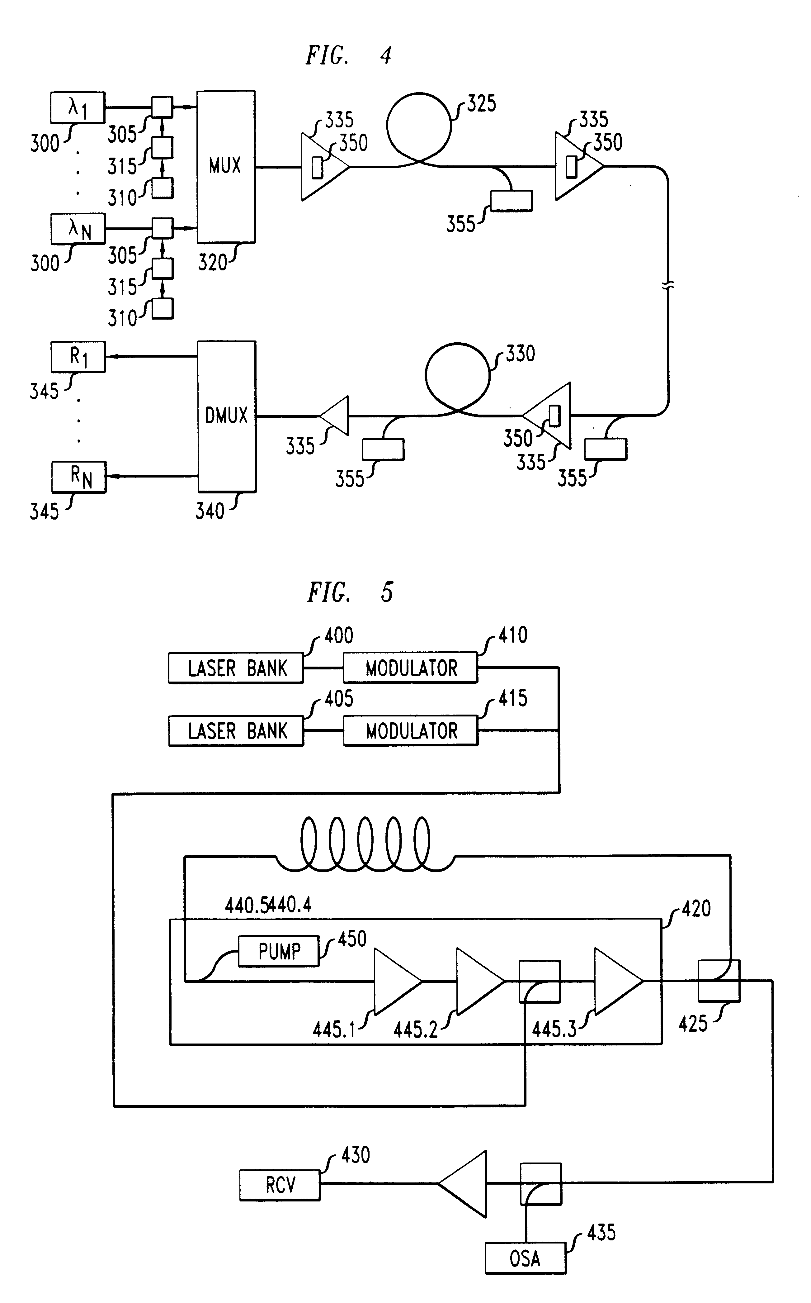
The first and second experiments described above were carried out using the laboratory prototype illustrated in FIG. 5. Forty-nine laser sources spanning the wavelength range 1541.75 nm-1561.01 nm at 50-GHz intervals were arranged in two banks 400, 405. The lasers were staggered such that one bank contained odd-numbered channels only, and the other contained even-numbered channels only. All lasers in each bank were modulated by a respective Mach-Zehnder modulator 410, 415. Using these modulators, data in the form of 2.sup.31 -1 pseudo-random bit sequences were encoded at a rate of 10 Gb / s. The combined output from modulators 410 and 415 was launched into a fiber loop, which included hybrid amplifier 420. At the output of amplifier 420, optical 10% coupler 425 diverted a portion of the signal to receiver 430 and optical spectrum analyzer 435. The fiber span included five sections 440.1-440.5 of dispersion-shifted fiber having an effective cross-sectional area of about 50 square micro...


PUM


Abstract

In an optical communication system, the signal power level injected into each of one or more optical fiber spans is reduced so as to suppress undesired non-linear effects. This reduction in injected signal level is made possible by remotely pumped amplification in the spans that are affected.

Description

This invention relates to optical communication systems whose performance is susceptible to degradation by non-linear optical effects. More particularly, the invention relates to systems that, moreover, employ wavelength division multiplexing (WDM).ART BACKGROUNDWith reference to FIG. 1, a typical optical fiber communication system includes a source 10 of information-carrying optical signals, and an optical fiber transmission line 15 for transporting the signals to at least one optical receiver 20. Where long-haul transmissions are contemplated, e.g., transmissions over distances on the order of one hundred kilometers or more, it is typical to include repeaters 25 for signal recovery and amplification. A fiber span 30 extends between each adjacent pair of repeaters, and typically also from the source to the first repeater. It is frequent practice for each fiber span to be terminated, within a repeater, by an optical amplifier 35, 40. Such an optical amplifier is typically a discrete...

Claims


Application Information

Patent Timeline
IPC IPC(8): H04B10/18H04B10/17H04B10/02H04B10/12H04B10/135H04B10/14H04B10/2581H04J14/00H04J14/02
CPCH04B10/2543H04B10/2935
Inventor HANSEN, PER BANGNIELSEN, TORBEN N.STENTZ, ANDREW JOHN
Owner ALCATEL-LUCENT USA INC
Why Eureka
Try Eureka