
Sliding sleeve with sleeve protection

a technology of sliding sleeves and sleeves, applied in the direction of valve operating means/release devices, sealing/packing, wellbore/well accessories, etc., can solve the problems of poor withstanding the flow of petroleum fluid, high maintenance costs of such valves, and sensitive wear and tear

Inactive Publication Date: 2001-12-04
SCHLUMBERGER TECH CORP
View PDF5 Cites 41 Cited by
  • Summary
  • Abstract
  • Description
  • Claims
  • Application Information

AI Technical Summary

Benefits of technology

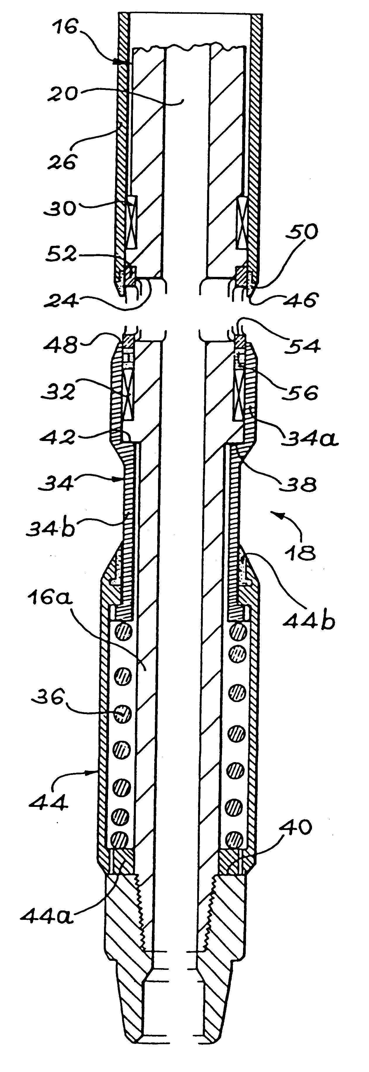
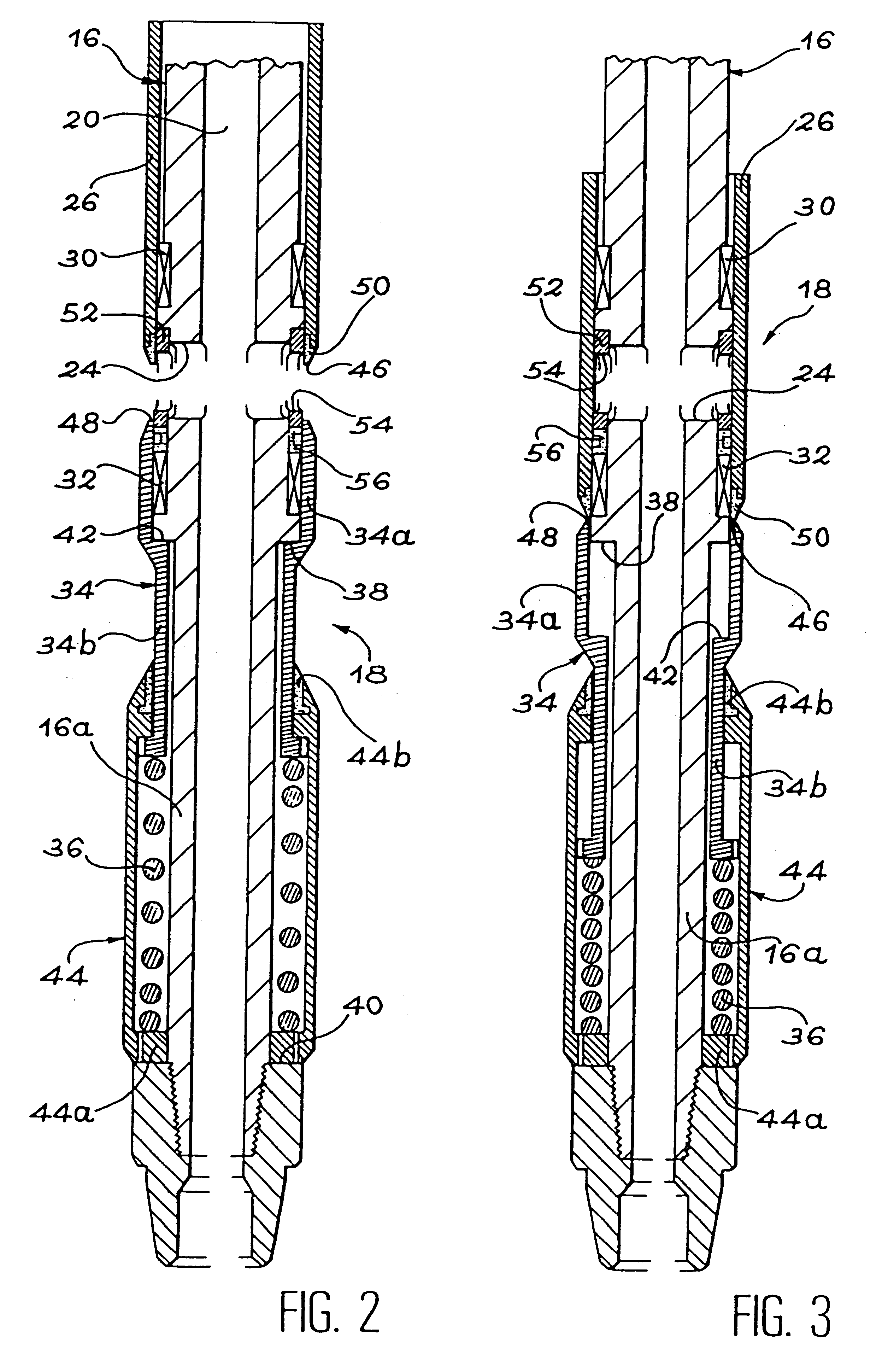
By means of this configuration, the first sealing means are always covered either by the closure sleeve, when the device is in the closed state, or by the protective sleeve, when the device is open, or else by both sleeves in end-to-end abutment, when the device is almost closed. The sealing means are thus never directly subjected to the flow of the petroleum fluid. Any abrasion wear on the sealing means is thus limited. In addition, the sealing means are permanently compressed so that any fatigue wear is prevented.
In this configuration, the front edge of the closure sleeve is advantageously formed on a separate annular portion made of a material having high resistance to erosion wear, such as a ceramic. This characteristic makes it possible to improve the life-span of the closure sleeve significantly.
In comparable manner, in order to reduce the wear on the holes formed in the production tubing, a separate ring made of a material having high resistance to wear may be associated with the production tubing and interposed between said tubing and the closure sleeve at the same level as the hole. The separate ring is then provided with another hole that faces said hole and that is smaller in section.

Problems solved by technology

Any maintenance on such valves is costly (removal and re-insertion of the production tubing), and it results being interrupted, which goes against the object that they are supposed to achieve (optimized well profitability).
One of the essential problems lies in the need to provide dynamic sealing gaskets on the production tubing, on either side of the holes formed therein, so that the valve is properly closed when the closure sleeve occupies the corresponding position.
They are thus very fragile.
In particular, they are very sensitive to wear, to abrasion, and to fatigue, and they are very poor at withstanding the flow of the petroleum fluid.
That accelerates fatigue in the gasket and causes it to wear prematurely.
The gasket is thus subjected to abrasion which accelerates wear on it.
Another problem appears when the valve is opened after being closed for a certain amount of time.
If no particular precaution is taken, the gasket is then torn away or else it wears very rapidly.
However, such rings are not very effective, and they do not prevent the gasket from suffering accelerated damage as a result of the valve being opened.
Another problem caused by the use of a closure sleeve that is provided with holes is constituted by the edges of the holes wearing rapidly under the effect of the flow of the petroleum fluid.
However, that also has a detrimental effect on the gaskets which tend to be cut by the beveled edges of the holes in the closure sleeve when said edges arrive at the gaskets.
Any abrasion wear on the sealing means is thus limited.

Method used


Image

  • Sliding sleeve with sleeve protection
  • Sliding sleeve with sleeve protection
  • Sliding sleeve with sleeve protection

Examples


Embodiment Construction

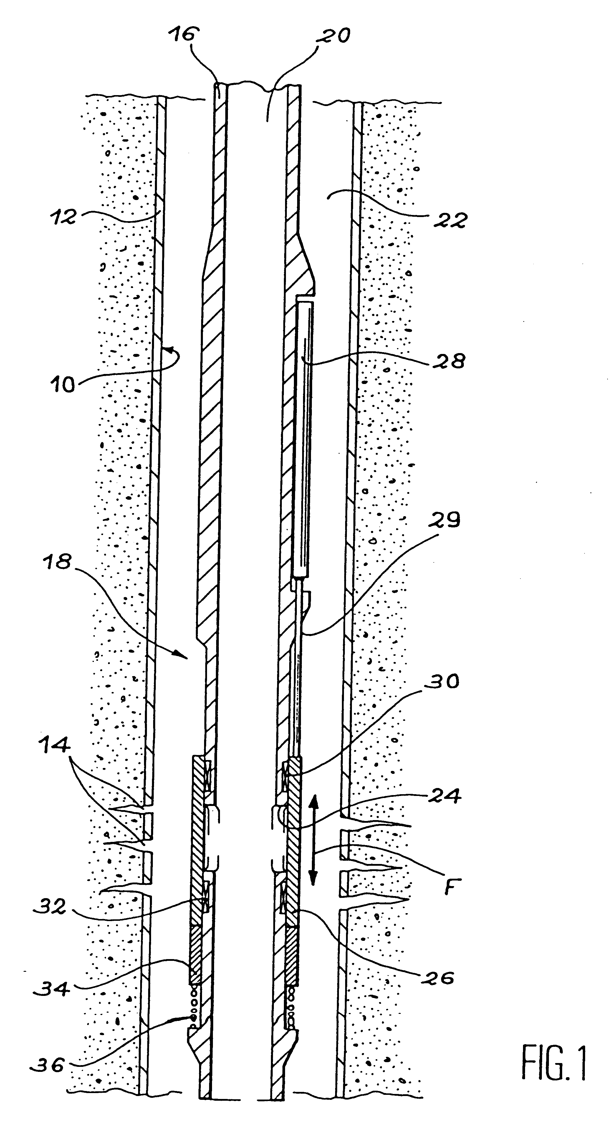
In FIG. 1, reference 10 designates an oil well in production, only a bottom region of which is shown. It should be noted that said bottom region may extend vertically, as shown, or horizontally, or on a slope, without going beyond the ambit of the invention. When the flow rate control device is placed in a horizontal or deviated region of a well, the expressions such as "downwards" and "upwards" used in the following description then mean respectively "away from the surface" and "towards the surface".

The walls of the oil well 10 are reinforced with casing 12. In the region of the well shown in FIG. 1, the casing 12 is perforated at 14 so as to cause the well to communicate with a natural deposit of petroleum fluid (not shown).

To enable the petroleum fluid to be conveyed to the surface, production tubing 16 is received coaxially in the well 10 over its entire depth. The production tubing 16 is made up of a plurality of tubing segments interconnected end-to-end. One of the segments, s...


PUM


Abstract

A flow rate control device (18) placed at the bottom of an oil well in production comprises holes (24) formed in the production tubing (16), a closure sleeve (26) suitable for sliding over the holes (24) for controlling the flow rate, and a protective sleeve (34). The protective sleeve (34) is urged by a return spring (36) into a position in which it covers a sealing gasket (32). During closure of the device (18), the two sleeves come into edge-to-edge abutment and the closure sleeve (26) pushes the protective sleeve (34) back against the return spring (36). The sealing gasket (32) is never in direct contact with the fluid in the well. Preferably, the closure sleeve (26) is mounted on the outside of the production tubing (16).

Description

The present invention relates to a device designed to control the downhole flow rate of a petroleum fluid via production tubing.Such a device may, in particular, be used in an oil well in production to optimize the production of the well over time. It is particularly applicable to the case when the petroleum fluid penetrates into a vertical, horizontal, or deviated well at at least two locations.STATE OF THE ARTValves of the on-off type are usually used down oil wells before they are brought on stream. Such valves are installed on the production tubing, where, either initially or at the end of the life of the well (when too much water is produced), they can close off the passage between the inside of the tubing and the annular space that surrounds it. Such a valve usually comprises a slidably-mounted sleeve placed inside the production tubing, and holes formed in the tubing at the level of the sleeve.When the valve is to be driven in the opening direction or in the closing direction...

Claims


Application Information

Patent Timeline
Patent Type & Authority Patents(United States)
IPC IPC(8): E21B34/00E21B34/06
CPCE21B34/06
Inventor RAYSSIGUIER, CHRISTOPHE
Owner SCHLUMBERGER TECH CORP
Learn More