

Method and system for controlling a tuning voltage of a phase-locked loop circuit to an optimal value
- Summary
- Abstract
- Description
- Claims
- Application Information
AI Technical Summary
Problems solved by technology
Method used
Image

Examples
Embodiment Construction
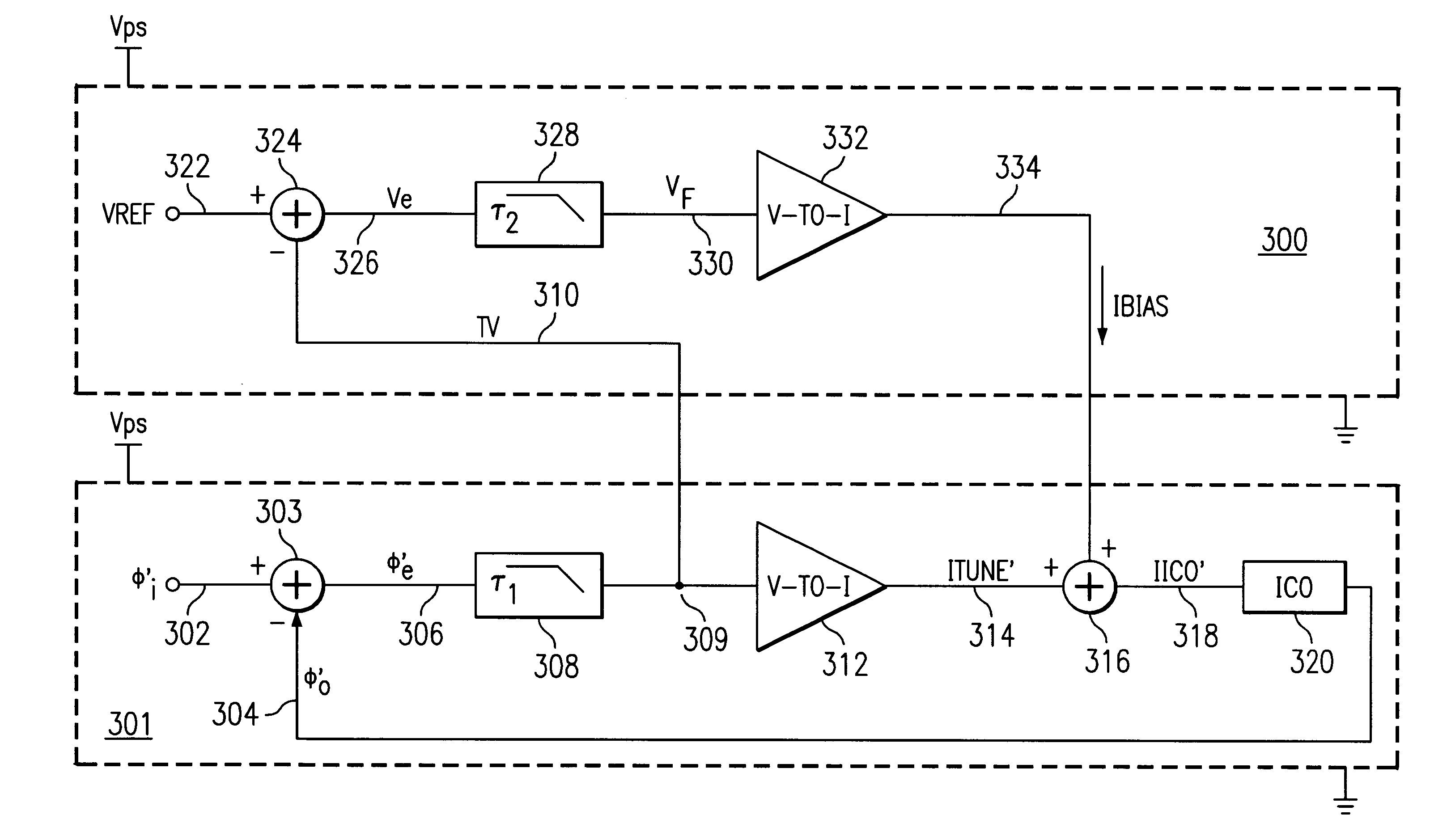
A method and system for controlling a tuning voltage of a phase-locked loop circuit to an optimal value are disclosed. Minimum and maximum bias current values are defined for a bias current from a linear control loop circuit, that is a tuning voltage circuit which controls the tuning voltage of the phase-locked loop circuit. The linear control loop circuit is coupled to the phase-locked loop circuit. The linear control loop circuit infinitely varies a current value for a current-controlled oscillator of the phase-locked loop circuit. The current value is based on a tuning current of the phase-locked loop circuit and the bias current. The bias current infinitely varies in value between the minimum bias current value and the maximum bias current value to direct the tuning voltage to an optimal value.
With reference now to FIG. 3, an exemplary tuning voltage ("TV") circuit 300, which is an analog, linear, and voltage control loop, for controlling a tuning voltage of a phase locked loop ...
PUM
 Abstract
Description
Claims
Application Information