Soft-switched quasi-single-stage (QSS) bi-directional inverter/charger

a bi-directional inverter and charger technology, applied in the field of bi-directional converters, can solve problems affecting its performance and desirability

Inactive Publication Date: 2001-12-11
VIRGINIA TECH INTPROP INC
View PDF2 Cites 252 Cited by
  • Summary
  • Abstract
  • Description
  • Claims
  • Application Information

AI Technical Summary

Problems solved by technology

However, as discussed herein below, this arrangement has severe limitations which affect its performance and desirability.

Method used


Image

  • Soft-switched quasi-single-stage (QSS) bi-directional inverter/charger
  • Soft-switched quasi-single-stage (QSS) bi-directional inverter/charger
  • Soft-switched quasi-single-stage (QSS) bi-directional inverter/charger

Examples


Embodiment Construction

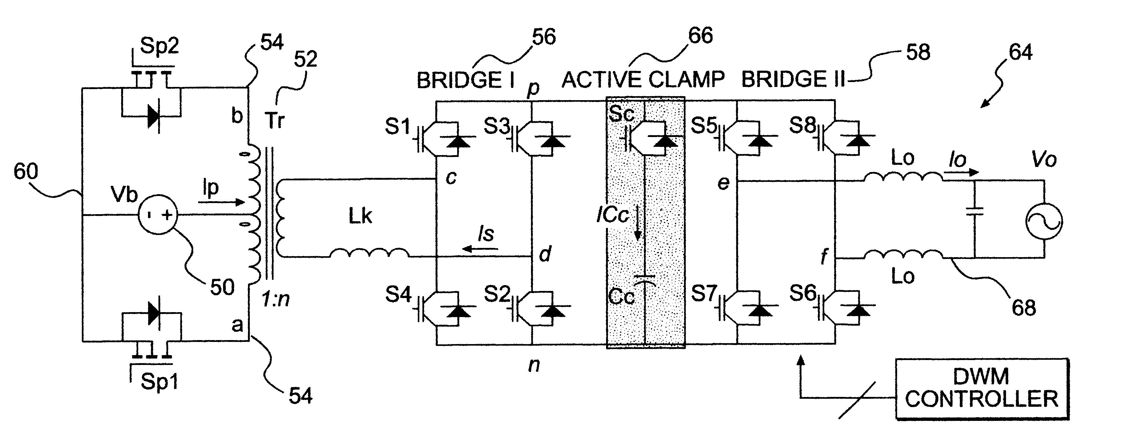
To facilitate discussion and comparison, a prior art bi-directional cycloconverter-based single-stage inverter / chargers with a bi-directional active clamp is drawn in FIG. 3. Considering the fact that the dc side 30 is usually a low voltage, e.g. 12 V or 24 V, battery, a voltage-fed push-pull topology is justified; the ac side 32 voltage is usually much higher, e.g. 110 V or 220 V, a full-bridge cycloconverter can be used, especially in cases where the power level is relatively high. Because it is desired to achieve rectification with power factor correction (PFC) when the converter operates in charger mode, the output side has to be current-fed to achieve the required boost action.

The bi-directional active clamp circuit 34 consists of four active switches, S.sub.C1 -S.sub.C4, four directing diodes, D.sub.1 -D.sub.4, and a clamp capacitor, C.sub.C. Coupled with suitable PWM scheme, it can suppress the otherwise high transient voltage in the cycloconverter and achieve secure operatio...


PUM


Abstract

A soft-switched single-phase quasi-single-stage (QSS) bi-directional inverter/charger converts AC-DC or DC-AC. The inverter/charger comprises a push-pull inverter/rectifier on the dc-side, an isolation transformer which provides ohmic isolation and voltage scaling, two full-bridges on the ac side in cascade, a voltage clamp branch comprising a capacitive energy storage element in series with an active switch with its anti-parallel diode, a passive filter at the ac side to smooth out the high frequency switching voltage ripple at the output, and a corresponding PWM scheme to seamlessly control the converter to operate in all four quadrant operation modes in the output voltage and output current plane, and is capable of converting power in both directions.

Description

1. Field of the InventionThe present invention generally relates to a bidirectional power converter and, more particularly, to a cycloconverter which is capable of acting as both an inverter (converting DC power to AC power) and as a rectifier (converting AC power to DC power).2. Description of the Prior ArtBi-directional inverters / chargers are increasingly used in line-interactive uninterruptible power systems (UPSs), battery-backup stand-alone inverter systems, and alternative energy systems such as wind power and photovoltaic applications. A simplified block diagram of such a system is shown in FIG. 1. When voltage the bi-directional inverter / charger 2 functions as an inverter, it converts the dc voltage, V.sub.b, into an ac output voltage, V.sub.0, at line frequency to supply loads with various power factors. The dc source can be a low-voltage battery, or an alternative energy source with battery backup. Once the alternative ac source of V.sub.g, which can be standalone engine-g...

Claims


Application Information

Patent Timeline
Patent Type & Authority Patents(United States)
IPC IPC(8): H02M7/797H02J9/06H02M5/458H02M3/24H02M3/335H02M7/48H02M5/00H02M7/66
CPCH02J9/062H02M3/33584H02M5/4585H02M7/4807H02M7/797
Inventor WANG, KUNRONGLEE, FRED C.
Owner VIRGINIA TECH INTPROP INC
Why Eureka
Try Eureka