Stage apparatus, scanning type exposure apparatus, and device produced with the same

a technology of scanning type and exposure apparatus, which is applied in the direction of photomechanical apparatus, instruments, printing, etc., can solve the problems of large size of wafer stage for holding the wafer, reverse deterioration of throughput, and heavy weight of the wafer stag

Inactive Publication Date: 2001-12-18
NIKON CORP
View PDF31 Cites 166 Cited by
  • Summary
  • Abstract
  • Description
  • Claims
  • Application Information

AI Technical Summary

Problems solved by technology

However, the scanning exposure is not performed during the period corresponding to the movement distance during the pre-scanning and during the over-scanning.
The elongation of the distance causes an inconvenience such that the throughput is reversely deteriorated.
Accordingly, there is such a tendency that the wafer stage for holding the wafer has a large size and a heavy weight.
Accordingly, there is such a tendency that the wafer stage necessarily has a large size and a heavy weight.
The large size and the heavy weight of the wafer stage as described above necessarily deteriorate the response performance in the positional control for the wafer stage.
For this reason, the settling time is prolonged, resulting in such an inconvenience that the throughput is reversely deteriorated although the rate of acceleration, the rate of deceleration, and the maximum velocity are originally increased in order to improve the throughput.
It has been feared that the large size of the wafer stage brings about the inconvenience such as the increase in movement area of the wafer stage, and consequently the increase in installation area for the apparatus (increase in foot pr...

Method used


Image

  • Stage apparatus, scanning type exposure apparatus, and device produced with the same
  • Stage apparatus, scanning type exposure apparatus, and device produced with the same
  • Stage apparatus, scanning type exposure apparatus, and device produced with the same

Examples


first embodiment

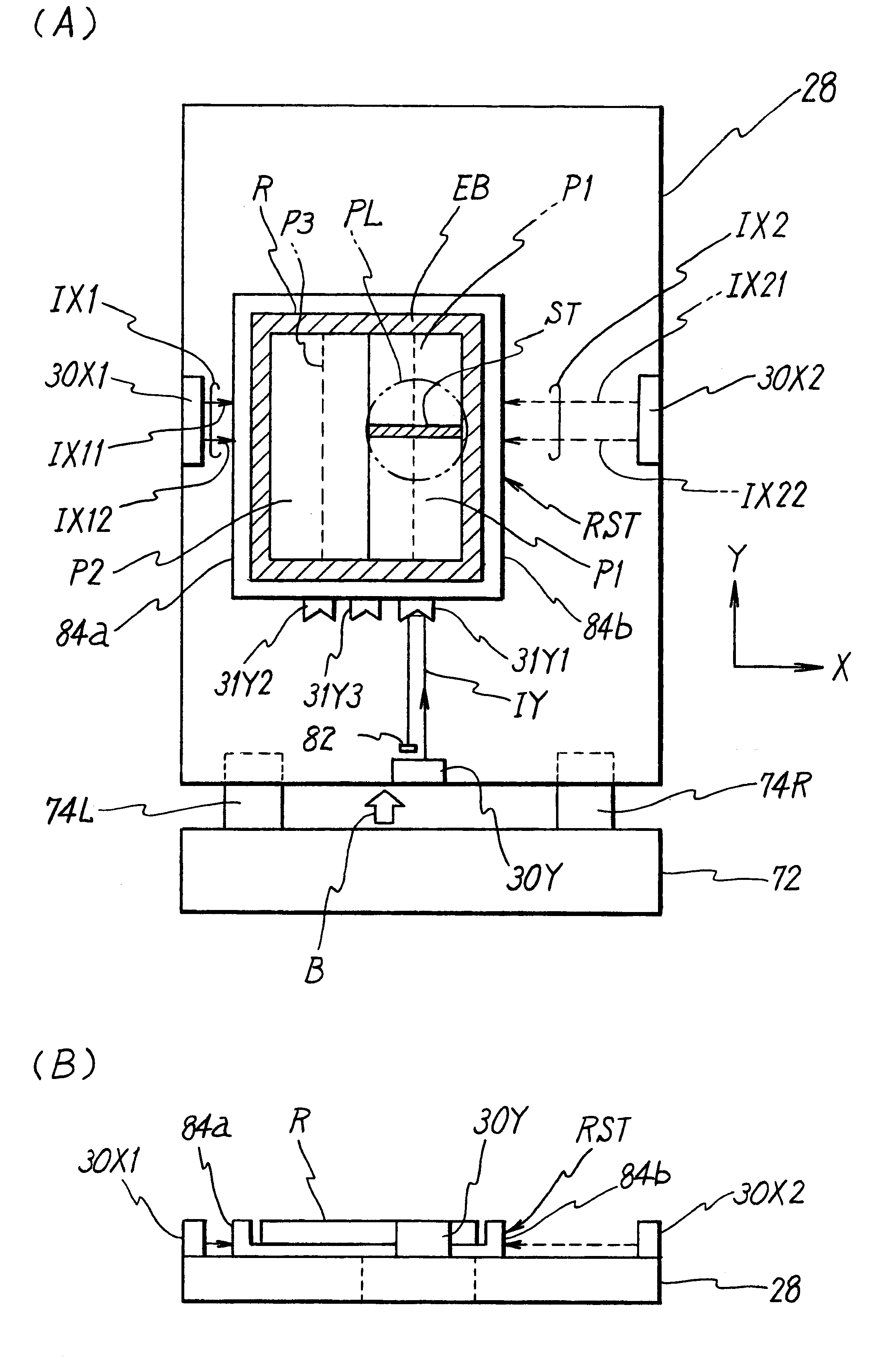
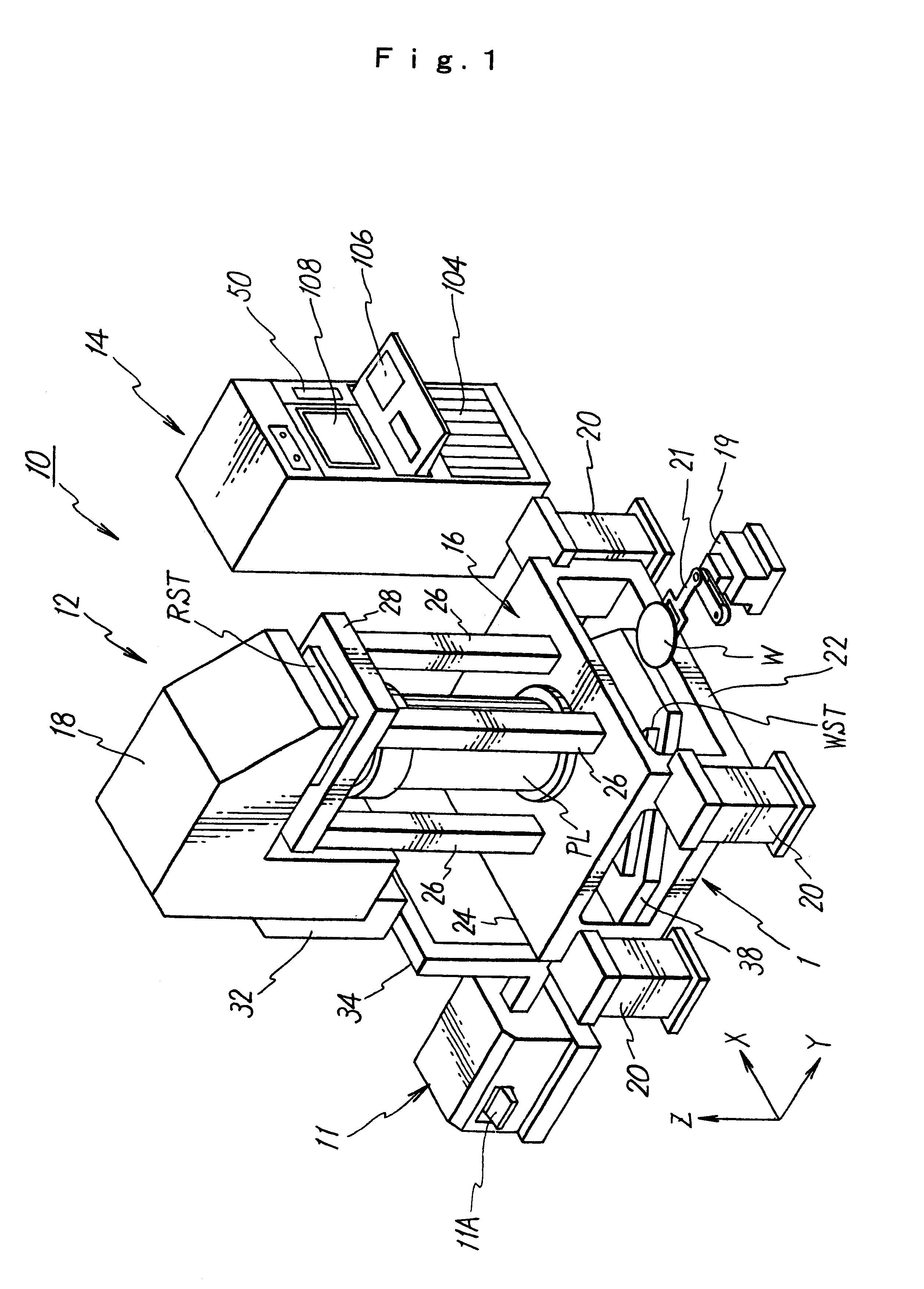
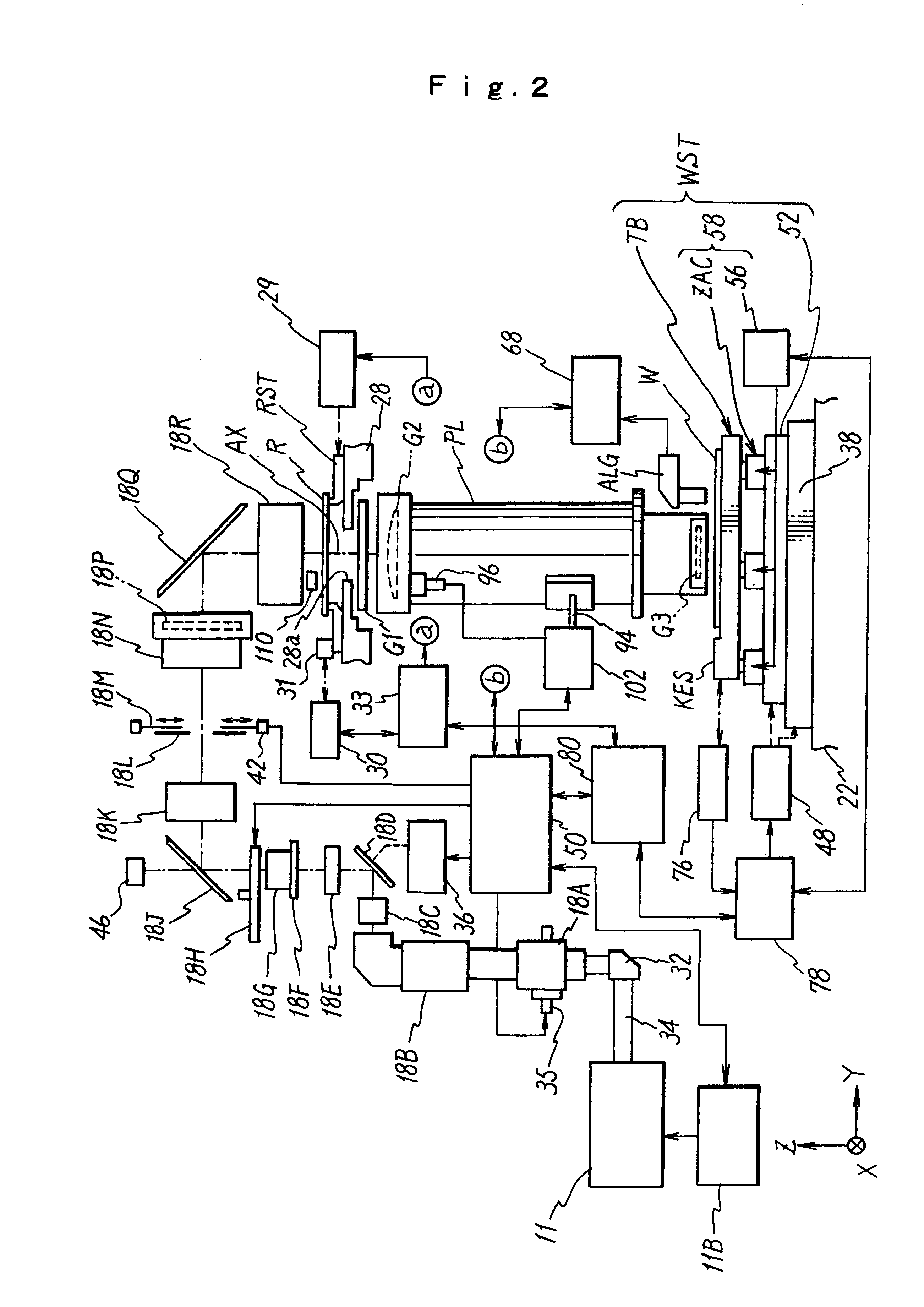
In the first embodiment, the first to fourth concepts are specified. FIG. 1 shows a perspective view illustrating a scanning type exposure apparatus 10 according to an embodiment of the present invention. FIG. 2 schematically shows an internal arrangement of the scanning type exposure apparatus 10. The scanning type exposure apparatus 10 is a projection exposure apparatus for performing the exposure operation in accordance with the step-and-scan manner which is being dominantly used as a lithography apparatus for producing semiconductor devices. The scanning type exposure apparatus 10 transfers an entire circuit pattern on a reticle R to a plurality of shot areas on a wafer W respectively in accordance with the step-and-scan manner by relatively scanning the reticle and the wafer W in the one-dimensional direction (Y direction in this case) with respect to the field of a projection optical system PL while projecting a part of the circuit pattern depicted on the reticle R as the mask...

second embodiment

The second embodiment described above is illustrative of the case in which the wafer stages WST1, WST2 as the first movable members for constructing the stage apparatus 101 are driven by the planar magnetically floating type linear actuators. However, the stage apparatus according to the present invention is not limited thereto. The driving unit for driving each of the first movable members may be, for example, an ordinary linear motor.

The second embodiment described above is illustrative of the case in which the scanning exposure is performed in accordance with the step-and-scan system. However, the applicable range of the stage apparatus according to the present invention is not limited thereto. It is a matter of course that the present invention is also applicable equivalently, for example, to the projection exposure apparatus such as a stepper for performing the stationary exposure in accordance with the step-and-repeat system, the proximity exposure apparatus for transferring t...


PUM


Abstract

An exposure apparatus has a triangular shaped stage which is movable in a two-dimensional plane while holding a substrate. The stage has a reflecting surface provided on a side face of the stage so that the surface extends in a specific direction intersecting Y axis and X axis. An interferometer radiates a beam onto the reflecting surface to measure a position of the stage in a direction perpendicular to the specific direction. Using the measured position and an angle of the specific direction, a calculator can calculate the position of the stage on rectangular coordinate system defined by X and Y axes. The size and weight of the stage can be reduced, and the throughput of the exposure apparatus is improved.

Description

FIELD OF THE INVENTIONThe present invention relates to a scanning type exposure apparatus and a scanning exposure method used when a circuit device such as a semiconductor circuit element and a liquid crystal display element is produced in accordance with a lithography step. In particulars the present invention relates to a scanning type exposure apparatus and an exposure method preferably used to perform scanning exposure with a large mask having a size of not less than 9 inches. The present invention also relates to a device produced with the exposure method.Especially, the present invention generally includes the following five concepts in order to achieve the common objects of the present invention as described later on. The first concept relates to a scanning exposure method and a scanning exposure apparatus in which a substrate is moved in synchronization with a mask having a large pattern or a plurality of comparted patterns so that the large pattern is transferred to the sub...

Claims


Application Information

Patent Timeline
IPC IPC(8): G03F7/20H01L21/67H01L21/68
CPCG03F7/70358G03F7/707G03F7/70708G03F7/70716G03F7/70725G03F7/70766G03F7/70775H01L21/681G03F7/70258
Inventor NISHI, KENJI
Owner NIKON CORP
Why Eureka
Try Eureka