Rapid sub pixel edge detection and locating method based on machine vision

A sub-pixel edge, machine vision technology, used in instruments, image enhancement, image analysis, etc., can solve the problems of low detection and positioning accuracy, slow processing speed, etc.

Active Publication Date: 2015-01-07
湖南湘江时代机器人研究院有限公司
View PDF3 Cites 40 Cited by
  • Summary
  • Abstract
  • Description
  • Claims
  • Application Information

AI Technical Summary

Problems solved by technology

[0010] In view of the above problems, the present invention proposes a fast sub-pixel edge detection and positioning method based on machine vision, w

Method used


Image

  • Rapid sub pixel edge detection and locating method based on machine vision
  • Rapid sub pixel edge detection and locating method based on machine vision
  • Rapid sub pixel edge detection and locating method based on machine vision

Examples


Embodiment Construction

[0117] The present invention will be further described in detail below in conjunction with the drawings and specific implementation process.

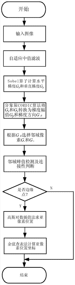
[0118] A fast sub-pixel edge detection and location method based on machine vision, comprising the following steps:

[0119] Step 1: Obtain the image of the PCB board to be inspected:

[0120] When the PCB board machine vision quality inspection and sorting system on the electronic manufacturing production line is running, the image of the PCB board to be inspected is obtained;

[0121] Step 2: Perform grayscale processing and denoising operations on the PCB board image to be detected to obtain a denoised image:

[0122] The adaptive median filtering method based on the template operation is used to remove the noise interference;

[0123] Step 3: Calculate the right-angle horizontal gradient G of each pixel in the horizontal direction on the denoised image x and a right-angled vertical gradient G in the vertical direction y ;

[01...


PUM


Abstract

The invention discloses a rapid sub pixel edge detection and locating method based on machine vision. The method includes the following steps that firstly, a detection image is acquired; secondly, denoising pretreatment is conducted on the image; thirdly, the gradient Gx of each pixel point in the horizontal direction and the gradient Gy of each pixel point in the vertical direction are calculated; fourthly, the gradient magnitude G0 and the gradient direction Gtheta of each pixel points under polar coordinates are calculated; fifthly, neighborhood pixel points of each pixel point are determined; sixthly, pixel-level edge points are determined; seventhly, the distance between a sub pixel edge point of each pixel-level edge point in the eight-gradient direction and the pixel-level edge point is calculated; eighthly, the distance d between each sub pixel edge point in the actual gradient direction Gtheta and the corresponding pixel-level edge point is calculated; ninthly, a cosine lookup table method is adopted for calculating rectangular coordinates of each sub pixel edge point in the actual gradient direction Gtheta, so that the image edge points are detected and sub-pixel-level localization is conducted. The whole method is high in calculation accuracy and speed.

Description


Claims


Application Information

Patent Timeline
Owner 湖南湘江时代机器人研究院有限公司
Why Eureka
Try Eureka