Method of estimating a life of ball screw included in electric injection molding machine and life estimating system

a technology of life estimation and ball screw, which is applied in the direction of mechanical equipment, gearing details, instruments, etc., can solve the problems of adversely affecting the quality of molding, damage to ball screw components, and the need to immediately stop the operation of the injection molding machin

Inactive Publication Date: 2001-12-25
TOSHIBA MASCH CO LTD
View PDF3 Cites 17 Cited by
  • Summary
  • Abstract
  • Description
  • Claims
  • Application Information

AI Technical Summary

Problems solved by technology

If the ball screw is damaged during a long period of use, it is expected that the operation of the injection molding machine must instantly be stopped.
If such a situation takes place, the broken ball screw must immediately be replaced with a new one, which interrupts the operation of the associated production line, adversely affecting the stability of the quality of moldings and may possibly cause damage in component parts associated with the ball screw.
It is difficult to estimate the life of the ball screw accurately only by the operator's intuition.
The usable ball screw is thrown away and time and labor is wasted for the unnecessary change of the usable ball screw if the usable ball screw is changed too early.
The ball screw will be broken and serious damage will be made to the associated component parts if the time for changing the ball screw is delayed excessively.
Particularly, an arithmetic procedure for calculating the fatigue life on the basis of the torque is very complicated and, if the life of the bearing is used for life estimation, many parameters in addition to the torque of the driving motor are necessary and the arithmetic procedure becomes further complicated.

Method used


Image

  • Method of estimating a life of ball screw included in electric injection molding machine and life estimating system
  • Method of estimating a life of ball screw included in electric injection molding machine and life estimating system
  • Method of estimating a life of ball screw included in electric injection molding machine and life estimating system

Examples


first embodiment

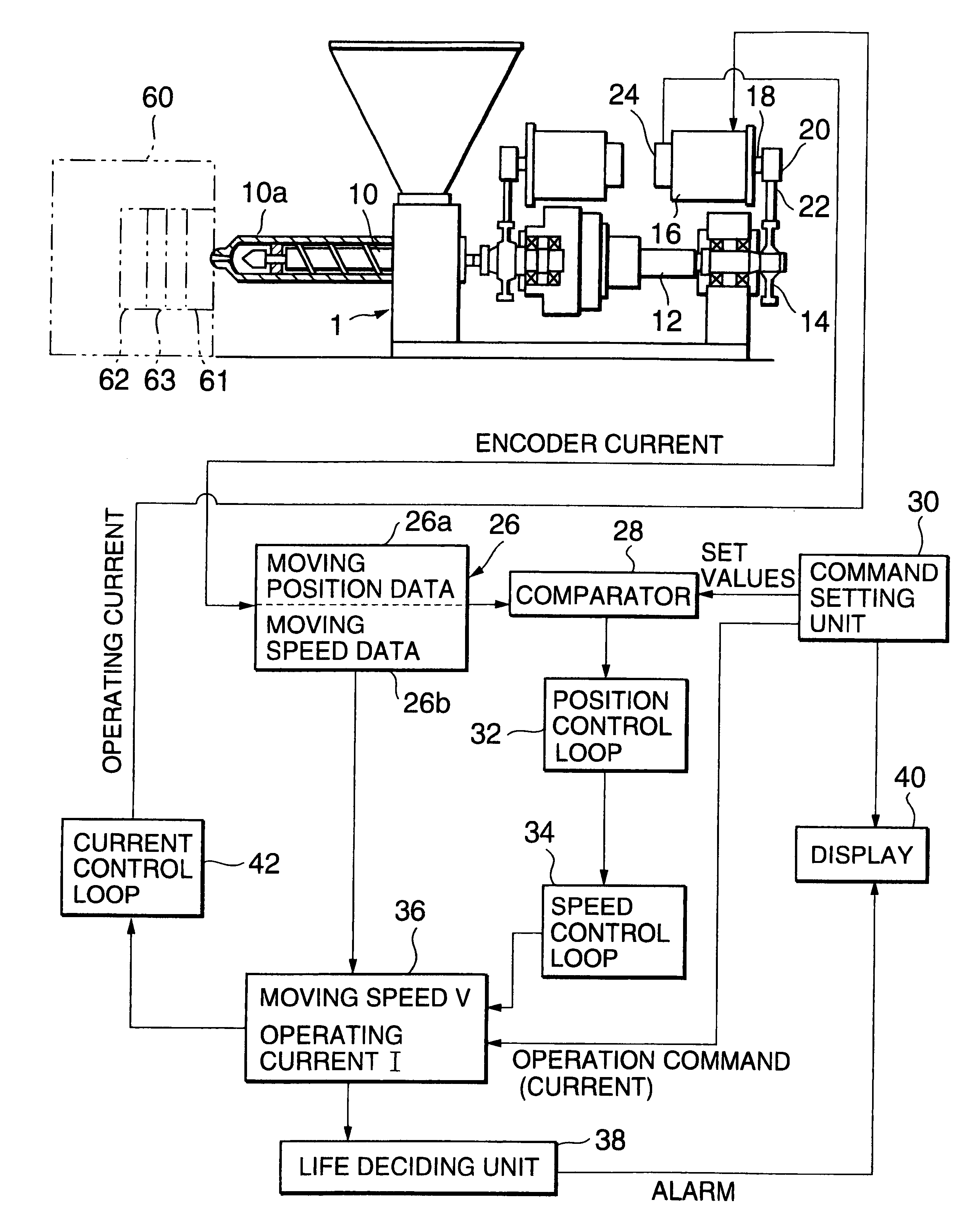
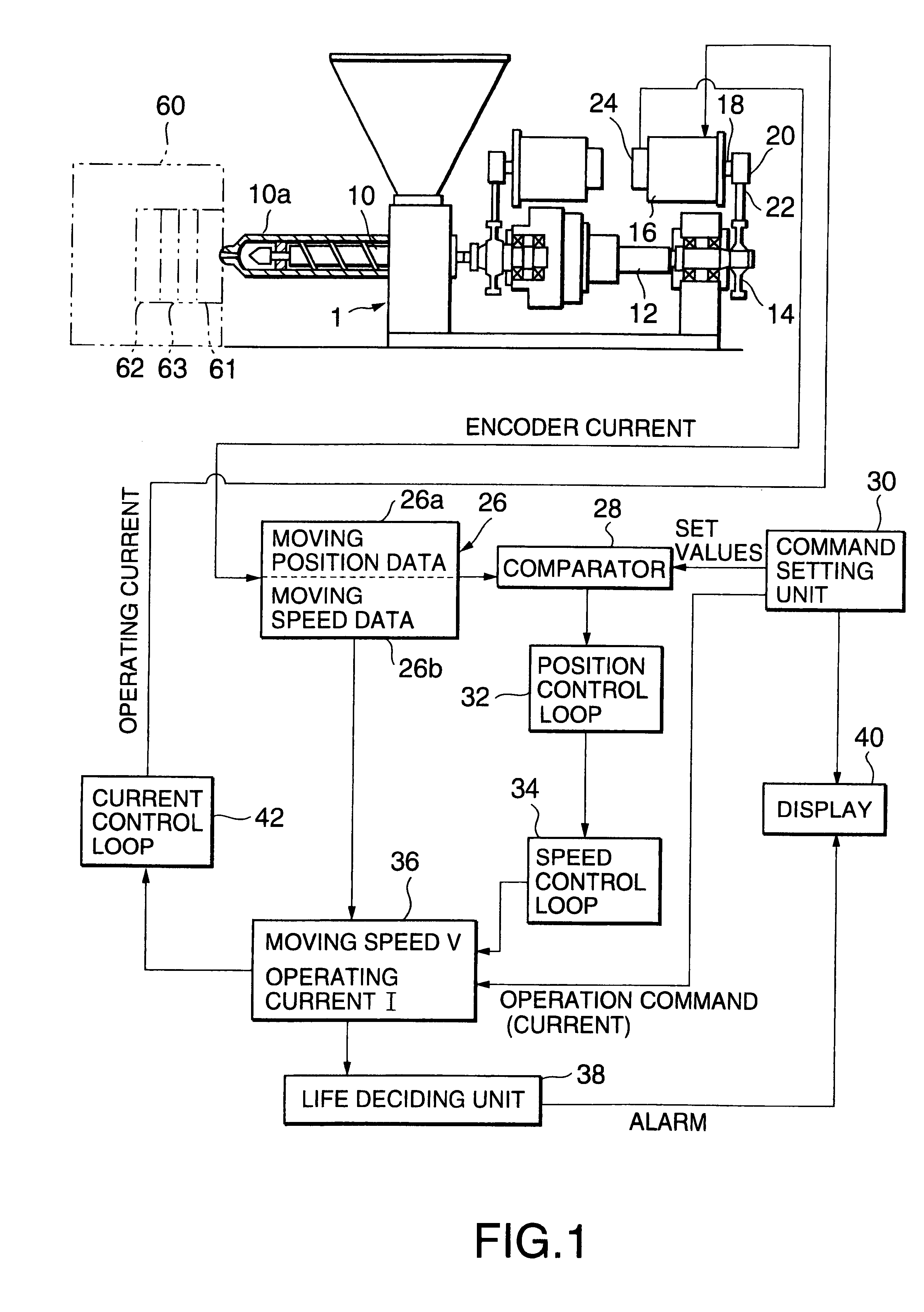
FIG. 1 is a schematic front elevation of an essential portion of a life estimating apparatus in a first embodiment according to the present invention for carrying out a life estimating method in accordance with the present invention for estimating the life of a ball screw included in an electric injection molding machine, and a block diagram of a control system, respectively.

Referring to FIG. 1, the electric injection molding machine has an injection unit 1 having a heating barrel 10a and an injection screw 10 placed for rotation in the heating barrel 10a, and an electric motor 16 operatively connected to the injection screw 10 by a ball screw 12 and a pulley 14.

The injection screw 10 is connected to the ball screw so as to be rotatably movable by the ball screw rotating. The pulley 14 is attached to one end of the ball screw 12. The electric motor 16 is disposed with its axis extended in parallel to the axis of the ball screw 12. A pulley 20 is attached to the output shaft 18 of th...

second embodiment

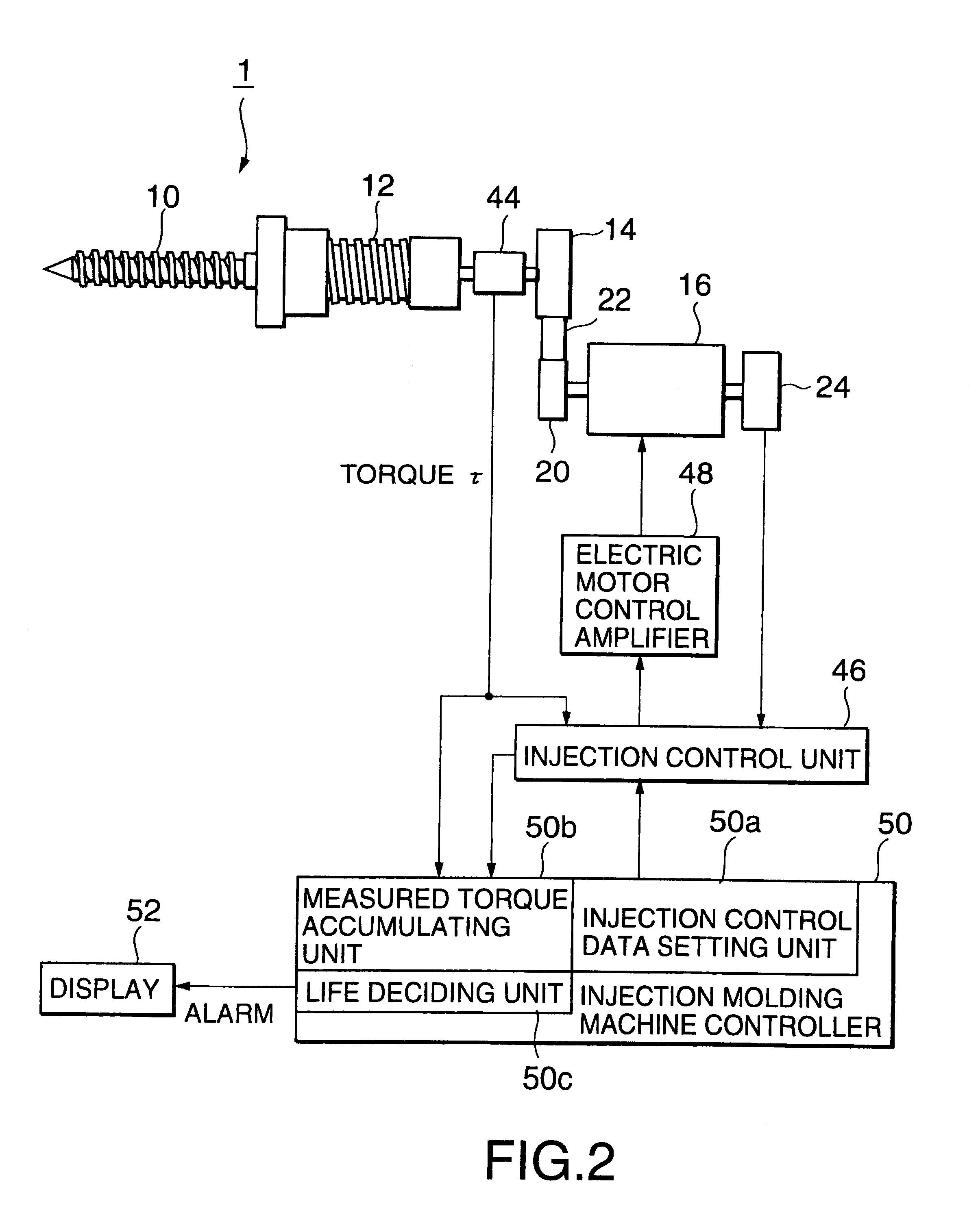
FIG. 2 is a block diagram of an essential portion of a life estimating apparatus in another embodiment according to the present invention for carrying out the life estimating method in accordance with the present invention for estimating the life of a ball screw included in an electric injection molding machine, and a control system. In the following description, parts shown in FIG. 2 like or corresponding to those shown in FIG. 1 are denoted by the same reference characters and the description thereof will be omitted.

Referring to FIG. 2, a torque measuring device (torque meter) 44 is interposed between the drive shaft side of an electric motor 16 and a ball screw 12.

The torque measuring device 44 measures torque .tau. needed to rotate the ball screw 12. Torque .tau. to be measured is proportional to driving current I for driving the electric motor 16. Therefore, a total energy value A' can be determined by accumulating products, each of a moving speed of the ball screw 12 in a unit...


PUM

PropertyMeasurementUnit
total energyaaaaaaaaaa
torqueaaaaaaaaaa
speedaaaaaaaaaa

Abstract

An injection unit including a heating barrel and an injection screw rotationally and axially movable and placed in the heating barrel is disposed on one side of a clamping mechanism for clamping a mold. The injection screw is driven and controlled for operation through a ball screw by an electric motor. Products, each of a moving speed of the ball screw and an operating current supplied to the electric motor in a unit time, are accumulated to calculate a total energy value indicating the amount of total energy supplied to the ball screw. A life energy value is predetermined on the basis of products, each of force generated by the ball screw and a moving speed of the ball screw. It is decided that a life of the ball screw has terminated when the total energy value A is equal to or greater than the life energy B (A>=B).

Description

1. Field of the InventionThe present invention relates to a method of estimating a life of a ball screw for moving an injection screw included in an electric injection molding machine and generating an alarm or the like, and a life estimating system for carrying out the method.2. Description of the Related ArtIn an electric injection machine, an injection screw is reciprocated axially by rotating a ball screw by an electric motor. Therefore, the greatest load is exerted on the ball screw during an injection molding operation. If the ball screw is damaged during a long period of use, it is expected that the operation of the injection molding machine must instantly be stopped. If such a situation takes place, the broken ball screw must immediately be replaced with a new one, which interrupts the operation of the associated production line, adversely affecting the stability of the quality of moldings and may possibly cause damage in component parts associated with the ball screw.To avi...

Claims


Application Information

Patent Timeline
Patent Type & Authority Patents(United States)
IPC IPC(8): F16H57/00G01N17/00B29C45/66B29C45/50B29C45/76
CPCB29C45/76B29C45/7666F16H57/01G01N17/00B29C45/5008B29C2945/7602B29C2945/76083B29C2945/7611B29C2945/76187B29C2945/76214B29C2945/76568B29C2945/76595B29C2945/76665B29C2945/76692B29C2945/76943F16H2057/012
Inventor TOTANI, TSUGINOBUSASAKI, KIYOSHIKANDA, AKIRAIIMURA, YUKIOKOIKE, JUNKATOH, FUMIYUKITAMAKI, MASAHIROYAMAGUCHI, YUTAKA
Owner TOSHIBA MASCH CO LTD
Why Eureka
Try Eureka