
Induction-hardened rolling bearing device

a rolling bearing and induction hardening technology, which is applied in the field of rolling bearing devices, can solve the problems of increasing the cost of dies in the cold drawing process, reducing the cold workability of steel materials, and insufficient rolling fatigue resistance life and wear resistance characteristics, etc., and achieves excellent cold drawability, long service life, and high wear resistance.

Inactive Publication Date: 2001-12-25
NSK LTD +1
View PDF17 Cites 25 Cited by
  • Summary
  • Abstract
  • Description
  • Claims
  • Application Information

AI Technical Summary

Benefits of technology

The present invention has been accomplished for overcoming the foregoing problems not yet solved and it is an object of the invention to provide an induction-hardened rolling bearing device, excellent in a cold drawability, having a long service life and high wear resistance, by dispersing particles of Ti carbide and Ti carbonitride into the steel material and applying induction hardening.

Problems solved by technology

In steel materials such as JIS-S53C described above, a hardness of about HRC 59 can be obtained as the surface hardness by properly controlling the heat treatment, but rolling fatigue resistant life and wear resistant characteristic are still insufficient.
Further, there is also a problem that the cold workability of the steel material is lowered as the carbon content increases and this leads to the increase in the die cost in the cold drawing process.
If the drawing speed is lowered with an aim of reducing the cost, the productivity is worsened.
However, a problem exists regarding the rolling fatigue characteristic.
Further, the steels for use in cold forging disclosed in Japanese Patent Unexamined Publication Hei 5-59486 are excellent in the hardenability but most of Ti merely added by from 0.02 to 0.05% is exhausted for fixing N required for incorporating B and no sufficient effect can be expected for the wear resistance.
It rather gives rise to a problem of increasing the possibility for the presence of Ti system non-metal inclusions having a size of several tens of micrometers which are deleterious to the rolling fatigue life.

Method used


Image

  • Induction-hardened rolling bearing device
  • Induction-hardened rolling bearing device
  • Induction-hardened rolling bearing device

Examples


Embodiment Construction

Preferred embodiments of the present invention are to be explained below.

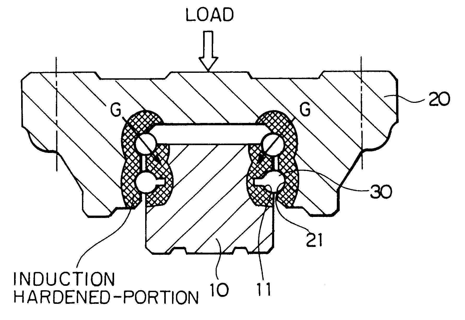
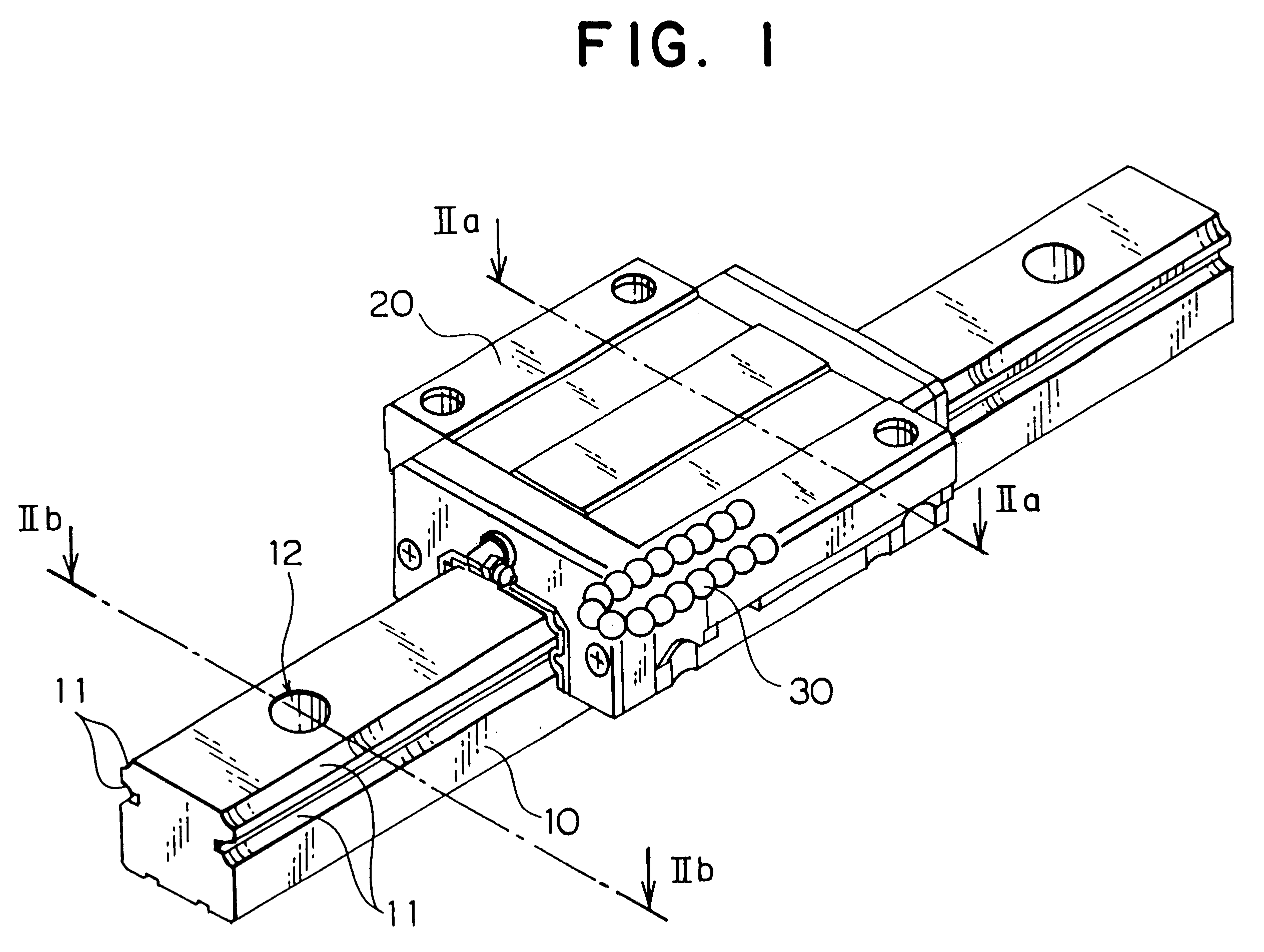
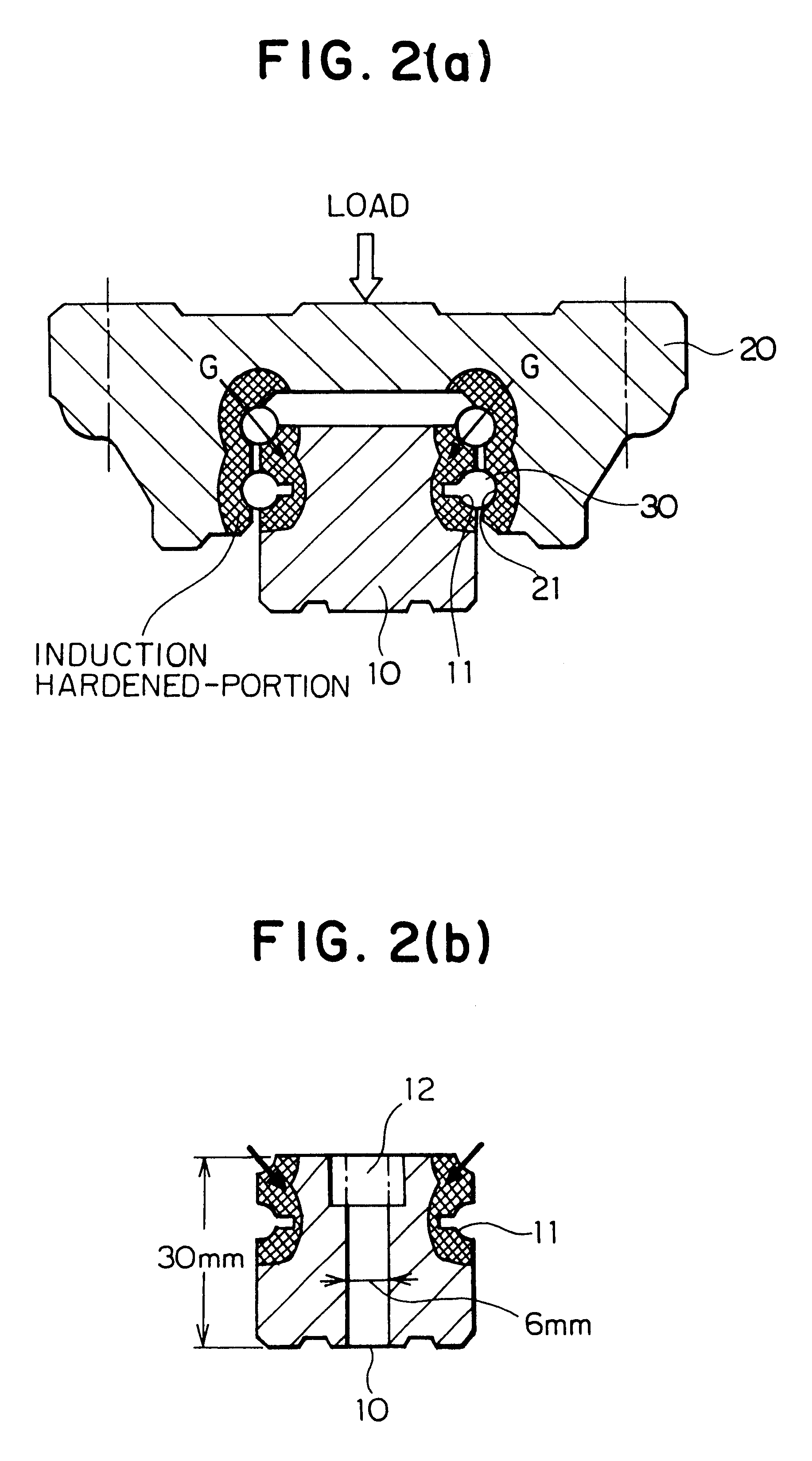
The rolling bearing device of the present invention include those devices comprising a raceway track member having a raceway surface on which rolling elements roll and a plurality of balls or rolls as rolling elements and adapted to conduct linear motion or rotational motion, particularly, those rolling bearing devices typically represented, for example, by the linear motion guide units, various types of ball bearings or roller bearings, ball screws, water pump bearings, uniform speed joint and bearings for use in automobile hub units described above, which are used by applying induction hardening to at least the raceway surface of the raceway track member.

The present invention intends to further improve the rolling fatigue life, the wear resistance and the cold drawability for the parts constituting the raceway surface of the rolling bearing devices raceway track members as constitutional parts in the rolling ...


PUM

PropertyMeasurementUnit
Fractionaaaaaaaaaa
Fractionaaaaaaaaaa
Fractionaaaaaaaaaa

Abstract

An induction-hardened rolling bearing device used by disposing rolling elements in a raceway track member, with excellent cold drawability and improved wear resistance and extended service life, in which ingredients of an alloy for the raceway track member contain, from 0.40 to 0.90% of C, from 0.05 to 0.80% of Si, from 0.10 to 2.0% of Mn, from 0.05 to 0.50% of Ti and 0.03% or less of N, on the weight basis, induction hardening is applied at least to the raceway surface of the raceway track member, and Ti carbide and Ti carbonitride each having an average particle diameter of from 5 to 100 nm are dispersed on the surface and in the steels of the raceway track member to make the hardness of the raceway surface to HRC 59 or more.

Description

1. Field of the InventionThe present invention concerns a rolling bearing device typically represented by linear motion guide units, as well as rolling bearings, ball screws, water pump bearings, uniform speed joint races and hub unit bearings for use in automobiles and, more in particular, it relates to an induction-hardened rolling bearing device which is excellent in wear resistance, has long service life, as well as excellent in cold drawability and capable of extending the serving life of a die by induction hardening.2. Statement of the Prior ArtHeretofore, a technique of applying induction hardening to parts made of carbon steels for use in mechanical structures, among all, medium carbon steels (C: 0.40 to 0.60%) as typically represented, for example, by automobile parts to increase the hardness only at the surface of them and improve static bending / twisting strength or rolling contact strength. For such application uses, steel materials such as JIS-S53C steels have been mainl...

Claims


Application Information

Patent Timeline
IPC IPC(8): C21D9/40F16C29/00F16C33/62C21D1/10C21D1/09F16C33/64
CPCC21D9/40F16C29/005F16C33/62F16C33/64C21D1/10Y10S384/913Y02P10/25
Inventor TAKEMURA, HIROMICHIMITAMURA, NOBUAKIMURAKAMI, YASUOYOSHIKAWA, TOMONOBUKITANO, SHUHEIHIRAOKA, KAZUHIKO
Owner NSK LTD
Learn More